
Videos
Determine the normal force, shear force, and moment at point C.
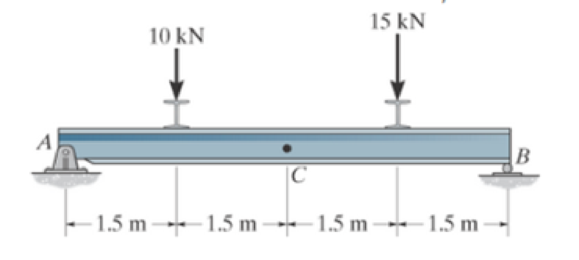
Prob. F7-1
The normal force, shear force, and moment at point C.
Answer to Problem 1FP
The normal force at point C,
The shear force at point C,
The moment at point C,
Explanation of Solution
Assumption:
- Consider the state of the member as tension, where the force is pulling the member, and as compression, where the force is pushing the member.
- The normal force is positive if it creates tension; a positive shear force acting on the segment causes it to rotate clockwise, and a positive bending moment acting on the segment will cause it to bend and concave upwards. Loadings that are opposite to these are considered negative.
- Consider the force indicating the right side as positive and the left side as negative, in the horizontal components of forces.
- Consider the force indicating upside as positive and downside as negative, in the vertical components of forces.
- Consider the clockwise movement as negative and the anti-clockwise movement as positive, wherever applicable.
- The method of sections can be used to determine the internal loadings.
Determine the reactions:
Entire beam:
Show the free body diagram of the entire beam as in Figure (1).
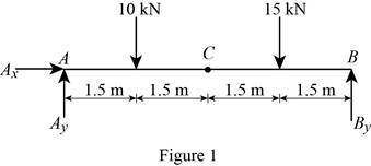
Using Figure (1),
Moment at point A:
Determine the vertical reaction at point B by taking the moment about point A.
Solve Equation (I).
Determine the forces and moment:
Segment CB:
Show the free body diagram of the segment CB as in Figure (2).
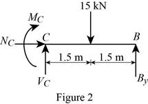
Using Figure (2),
Along the vertical direction:
Determine the shear force at point C by resolving the vertical component of forces.
Along the horizontal direction:
Determine the normal force at point C by resolving the horizontal component of forces.
Moment about point C:
Determine the moment at point C by taking the moment about point C.
Conclusion:
Substitute 13.75 kN for
Thus, the shear force at point C,
Refer to Equation (III).
Thus, the normal force at point C,
Substitute 13.75 kN for
Thus, the moment at point C,
Want to see more full solutions like this?
Chapter 7 Solutions
EP ENGR.MECH.-MOD.MASTERING ACCESS


- A single-pass crossflow heat exchanger is used to cool jacket water (cp = 1.0 Btu/lbm.°F) of a diesel engine from 190°F to 140°F, using air (Cp = 0.245 Btu/lbm.°F) at inlet temperature of 90°F. Both air flow and water flow are unmixed. If the water and air mass flow rates are 85500 lbm/h and 400,000 lbm/h, respectively, determine the log mean temperature difference for this heat exchanger. Assume the correction factor F to be 0.92. Air flow (unmixed) Water flow (unmixed) The log mean temperature difference of the heat exchanger is °F.arrow_forwardusing the theorem of three moments, find all the reactions and supports, I need concise calculations only. the answers are at the bottom, I need concise steps and minimal explanationsarrow_forwardIn an industrial facility, a counter-flow double-pipe heat exchanger uses superheated steam at a temperature of 155°C to heat feed water at 30°C. The superheated steam experiences a temperature drop of 70°C as it exits the heat exchanger. The water to be heated flows through the heat exchanger tube of negligible thickness at a constant rate of 3.47 kg/s. The convective heat transfer coefficient on the superheated steam and water side is 850 W/m²K and 1250 W/m²K, respectively. To account for the fouling due to chemical impurities that might be present in the feed water, assume a fouling factor of 0.00015 m² K/W for the water side. The specific heat of water is determined at an average temperature of (30+70)°C/2 = 50°C and is taken to be Cp J/kg-K. Water Steam Determine the heat exchanger area required to maintain the exit temperature of the water to a minimum of 70°C. The heat exchanger area required isarrow_forward
- Stress, ksi 160 72 150- 140 80 70 ༄ ྃ ༈ ཎྜ རྦ ༅ ཎྜ ྣཧྨ ➢ 130 120 110 100 90 2.0 2.8 3.6 4.4 5 Wire diameter, mm 6.0 6.8 2 7.6 8.4 Compression and extension springs. ASTM A227 Class II Light service Average service 0.020 0.060 0.100 0.140 0.180 0.220 0.260 0.300 0.340 0.380 0.420 0.460 0.500 Wire diameter, in Torsional stress due to initial tension, ksi 10 ४ 20 Preferred range 100 Stress, MPa 9.2 10.0 10.8 11.6 12.4 1100 1035 965 895 825 760 Severe service 690 620 550 50 150 3456789 10 11 12 13 14 15 16 Spring index, C = DJD FIGURE 18-21 Recommended torsional shear stress in an extension spring due to initial tension (Data from Associated Spring, Barnes Group, Inc.) 50 200 485 Stress, MPaarrow_forwardBolted Joint Design Bolted Frames Total Force due to door weight: P = 240 lb Number of Bolts: N = Distance to Bolt C/L: a = 4 N/A Bolt Material - Allowable shear stress of bolt material: T₂ = x Distance from Bolt centroid to bolt: x = y Distance from Bolt centroid to bolt: y = Degrees per Radian- Results y-Load on each bolt: F, = Moment resisted by bolt pattern: M = Radial distance from Bolt centroid to bolt: r = Sum squares of all radial distances: Σr² Force on each bolt to resist moment: F, - Angle for force composition: e= X-Force on each bolt to resist moment: F- y-Force on each bolt to resist moment: Fly Total y-Force on each bolt: Fy = Resultant force on bolt 1: R₁ = Required shear stress area for a bolt: A₂ = ASTM Grade A307 Steel 10,000 0 psi from Table 20-1 3.0 57.296 in degrees lb per bolt lb-in Formula FS-P/N M-Px XB r = (x² + y²)0.5 in² Σ 4r² Mr F₁ = Στ lb degrees lb lb lb Minimum Bolt Diameter: Din = Rounded up Bolt Diameter: D = 55 P. 1.5 in 2 in (3x) 1 in This bracket…arrow_forwardUniversity of Babylon Collage of Engineering/ Al-Musayab Department of Automobiles Final Examination/ Stage: 3rd Notes: Answer 4 questions only 2023-2202 Subject: Theory of vehicles Date: 2023\06\10-Saturday Time: Three Hours Course 2nd Attempt 1st Q1: A Hooke's coupling connects two shafts whose axes are inclined at 30°. The of the driven shaft? Find the maximum value of retardation or acceleration and driving shaft rotates uniformly at 600 rpm. What are the extreme angular velocities state the angle where both will occur. (12.5 Marks) Q2: Four masses, A, B, C, and D), revolve at equal radii and are equally spaced along a shaft. The mass B is 7 kg, and the radius of C and D make angles of 90° and 240°, respectively, with the radius of B. Find the magnitude of the masses A, C, and D and the angular position of A so that the system may be completely balanced. (12.5 Marks) Q3: A cam has straight worked faces that are tangential to a base circle of diameter 90 mm. The follower is a roller…arrow_forward
- Problem 18-26 Added Extension Springs Spring Material ASTM A227 Modulus of Elasticity of the Material in Shear: G 1.150E+07 psi Average Service Max Operating Load: F₁ = 100 lb Max Length between attachment points: L₁ = 60.00 in 20.00 lb 26.00 1.400 Min Operating Load: F₁ = Min Length between attachment points: L₁ = Maximum Outside Diameter = in in Results Note: you select a wire diameter from the "US steel wire gage" column in table 18-2 Formula k = AF/AL k = (F0-F1)/(Lo - L₁) Spring Rate: k = lb/in Assumed Trial Outside Diameter: OD = Assumed Trial Mean: D ma Assumed Design Stress in Spring: Tda in 1.070 in 102,000 psi Assumed Wahl Factor: K = 1.2 Calculated Wire Diameter: Dwa Actual Wire Diameter: Dw Actual outer diameter: OD = Actual inner diameter: ID= Spring Index: C = See Figure 18-8 Dw= [8KF Dm πTd 1/3 in 5' 5' 5' 5' This corresponds to US Steel 9 wire gage ID = Dm - Dw C = Dm/Dw 4C - 1 0.615 K = + 4C - с Wahl Factor: K = 8KFDm 8KFC T = TD πD Stress in Spring at F = Fo: To psi…arrow_forwardCHAIN DRIVE DESIGN Initial Input Data: Application: Garage Door Opener Drive type: AC Motor Driven machine Chain and Sprocket to pull the door up Degrees per Radian: 57.2958 degrees Sprocket Diameter: D = 1.690 in Number of strands: Chain number: 1 40 Service factor: 1.3 Table 7-10 No. of teeth Computed Data: Actual Motor Power Input: 0.000 hp Sprocket Speed (for sprocket attached to gear shaft) Design power: 0.00 rpm 0 hp 11 12 0.06 0.15 0.29 0.56 0.99 1.09 1.61 2.64 TABLE 7-7 Horsepower Ratings-Single Strand Roller Chain No. 40 0.500 inch pitch 10 25 50 100 180 200 300 500 700 900 1000 1: 0.06 0.14 0.27 0.52 0.91 1.00 1.48 2.42 3.34 4.25 4.70 ! 3.64 4.64 5.13 13 0.07 0.16 0.31 0.61 1.07 1.19 1.75 2.86 3.95 5.02 5.56 Design Decisions-Chain Type and Teeth Numbers: 14 Chain number: Use Table 7-7 Chain pitch: p = in 15 Number of Teeth: N = Per Table 7-7 16 0.08 0.20 0.39 0.75 1.32 1.46 2.15 3.52 0.07 0.17 0.34 0.66 1.15 1.28 1.88 3.08 0.08 0.19 0.36 0.70 1.24 1.37 2.02 3.30 4.55 5.80…arrow_forwardInput Data: Torque needed to overcome rolling friction in rollers, slides and other moving parts, except for Motor and Worm Gear the worm gear T₁ = Length of travel of door: Time for door to open or close: LD = 50 lb-in. 90 in t= 12.5 seconds Pitch diameter for chain sprocket: DPC 1.690 in Weight of Door: P = No. of worm threads: Nw = Worm Pitch diameter: Dw Diametral pitch: Pd Normal pressure angle: Degrees per Radian: Number of gear teeth: Calculated Data: Linear velocity of door and chain (in/sec): Linear velocity of door and chain (ft/min): Output Speed of Gear and Sprocket: Upward Force due to Weight of Door: Фо = = NG= 240 lb 2 1.250 in 12 14.5 degrees 57.2958 degrees 28 Vα= in/sec VC= ft/min NG = rpm FD lb Net Upward Force on Door: Fou lb Torque on gear ignoring rolling friction: TG = lb-in. Formula = FDU FD-2 x Fo (note: Fo is the Max Operating load of the extension springs). This is also the initial tension in the chain. TG = FDU X DPC/2 This is the also the torque on the…arrow_forward
- Q5/A: A car with a track of 1.5 m and a wheelbase of 2.9 m has a steering gear mechanism of the Ackermann type. The distance between the front stub axle pivots is 1.3 m. The length of each track arm is 150 mm, and the length of the track rod is 1.2 m. Find the angle turned through by the outer wheel if the angle turned through by the inner wheel is 30°. (6 Marks) Q5/B: Write True on the correct sentences and False on the wrong sentences listed below:- 1- In automobiles, the power is transmitted from the gearbox to the differential through bevel gears. 2- The minimum radius circle drawn to the cam profile is called the base circle. 3- The Proell governor, compared to the Porter governor, has less lift at the same speed. 4- The balancing of rotating and reciprocating parts of an engine is necessary when it runs at a slow speed. (6.5 Marks) ***Best of Luck *** جامعة بابل UNIVERSITY OF BABYLON Examiner: Mohanad R. Hameed Head of Department: Dr. Dhyai H. Jawadarrow_forwardUniversity of Babylon Collage of Engineering/ Al-Musayab Department of Automobiles Mid Examination/ Stage: 3rd Subject: Theory of Vehicles Date: 14 \ 4 \2025 Time: 1.5 Hours 2025-2024 Q1: The arms of a Porter governor are 250 mm long. The upper arms are pivoted on the axis of revolution, but the lower arms are attached to a sleeve at a distance of 50 mm from the axis of rotation. The weight on the sleeve is 600 N and the weight of each ball is 80 N. Determine the equilibrium speed when the radius of rotation of the balls is 150 mm. If the friction is equivalent to a load of 25 N at the sleeve, determine the range of speed for this position. Q2: In a loaded Proell governor shown in Figure below each ball weighs 3 kg and the central sleeve weighs 25 kg. The arms are of 200 mm length and pivoted about axis displaced from the central axis of rotation by 38.5 mm, y=238 mm, x=303.5 mm, CE 85 mm, MD 142.5 mm. Determine the equilibrium speed. Fe mg E M 2 Q3: In a spring loaded Hartnell type…arrow_forwardusing the theorem of three moments, find all the reactions and supports, I need the calculations onlyarrow_forward
 Elements Of ElectromagneticsMechanical EngineeringISBN:9780190698614Author:Sadiku, Matthew N. O.Publisher:Oxford University Press
 Mechanics of Materials (10th Edition)Mechanical EngineeringISBN:9780134319650Author:Russell C. HibbelerPublisher:PEARSON
 Thermodynamics: An Engineering ApproachMechanical EngineeringISBN:9781259822674Author:Yunus A. Cengel Dr., Michael A. BolesPublisher:McGraw-Hill Education
 Control Systems EngineeringMechanical EngineeringISBN:9781118170519Author:Norman S. NisePublisher:WILEY
 Mechanics of Materials (MindTap Course List)Mechanical EngineeringISBN:9781337093347Author:Barry J. Goodno, James M. GerePublisher:Cengage Learning
 Engineering Mechanics: StaticsMechanical EngineeringISBN:9781118807330Author:James L. Meriam, L. G. Kraige, J. N. BoltonPublisher:WILEY