
Calculate the average pressure at the bottom of the women’s high-heeled dress shoe and a women’s athletic walking shoe.
Answer to Problem 15P
The average pressure at the bottom of the women’s high-heeled dress shoe is
The average pressure at the bottom of the women’s athletic walking shoe is
Explanation of Solution
Given information:
Weight of the women is
Calculation:
The weight of the women is carried by both shoes. Hence, the weight (Force) acting on each shoe is as follows:
Sketch the profile of high-heeled dress shoe in inches as shown in Figure 1.
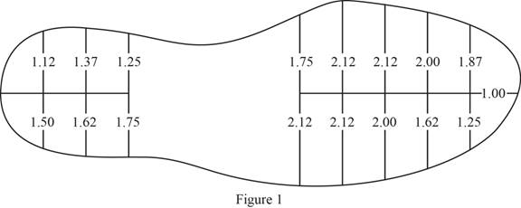
Refer to Figure 1.
The profile of contact area is divided into two equal parts and each part is divided into 8 trapezoids of equal heights.
Consider the area of top portion as
Apply trapezoidal rule as shown below.
Calculate the area of top portion
Calculate the area of bottom portion
Calculate the total area of high-heeled dress shoe as shown below.
Substitute
Calculate the average pressure at the bottom of high-heeled dress shoe as shown below.
Substitute
Hence, the average pressure at the bottom of the women’s high-heeled dress shoe is
Sketch the profile of athletic walking shoe in inches as shown in Figure 2.
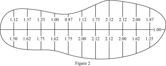
Refer to Figure 2.
The profile of contact area is divided into two equal parts and each part is divided into 12 trapezoids of equal heights.
Consider the area of top portion as
Calculate the area of top portion
Calculate the area of bottom portion
Calculate the total area of athletic walking shoe as shown below.
Substitute
Calculate the average pressure at the bottom of athletic walking shoe as shown below.
Substitute
Therefore, the average pressure at the bottom of the women’s athletic walking shoe is
Want to see more full solutions like this?
Chapter 7 Solutions
LMS Integrated for MindTap Engineering, 2 terms (12 months) Printed Access Card for Moavni's Engineering Fundamentals: An Introduction to Engineering, 5th

- Can you please explain how to draw the shear and moment diagrams. Thank you.arrow_forwardQ2: Design an activated sludge process to treat a waste flow of 15000 m³/day with a BODs of 180 mg/L following primary treatment. The effluent BOD, and SS are to be 20 m mg/L. Assume Xr = 15000 mg/L, X = 2500 mg/L, 0c = 10 day, Y = 0.60, kd=0.05. Determine 1- the reactor volume, 2- the Sludge production rate, 3- the circulation rate, 4- the hydraulic retention time, and 5- the oxygen required? C₁-Ce C 1 XV = 1 +0.532 QxC₁₂ VXF F= - 1+r (1+0.1r)² = Qr= dt Өс Qx Xr-X V R = [= Q YQ(So-S) Oc dx XV 1+Kd0c O₂demand =1.47 (So-S)Q-[1.14Xr(Qw)] Qw total sludge production/X, S = BOD, effluent - 0.63 * SS Warrow_forwardمارت حولة ملانول 60 Design Deceleration tank and screen for W.W.T.P of flow-144000 m² day Design Data: D.T=1-3 min 1-3b, d=1-1.5 m 60 Design Data: velocity= 0.6: 1.5 m/sec . A-Qdfv=b.d, b=2d 233 Design Data: bars used circular of p= 1.5:3 cm. rec. of (1:2 cm) x (2:6 cm) spacing between bars 2.5:5.0 cm fine screen, 2.5 7.5 cm coarse screen Sloping angle on hz (6)=45:60 = depth of water depth in approaching channel=d = ⚫nbars nspacings +1 ⚫b=nbars xo+nspacings I spacing net inclined area = 2 Aapproach channel=nspacing. spacing. L. 1=d/ sin Check: = 1.13 C 2.56 1134(6.05 P. 45.30 *velocity just befor the screen=v₁ = Qa(m³/sec) screen-b.d ≥ 0.6 m/sec. * velocity through the screen=v2 16mm use 2 Qa(m³/sec) nscreens (spacings Spacing).d ≤1.5 m/sec IsP. 22-65 12²² head losses = Ah = 1.4 x ≤0.1 m 2g bav usp = Ubar Q 23.65 k 148.72arrow_forward
- Q1: Design of trickling filter system single-stage with 3m depth, effluent BOD, of 20 mg/l, influent BODs =250mg/l, flow = 2.63 m³/min and hydraulic flow rate or hydraulic loading rate 25 m/day, r=3arrow_forward04 Q4 A waste effluent of 1.25 m/s with BOD, 183 mg/L, DO=0 mg/L and T = 20 °C is to be discharged into a river of 8 m³/s flow, BOD, = 2mg/L, DO -9.14 mg/L and T= 15 °C. At 20 °C, (K₁) is 0.3/day and (K2) is 0.9/day. The average velocity of the river is 0.8 m/s. 1) Is DO min within the environmental limitations? 2) At what distance is the maximum deficit located. 3) Draw the oxygen sag curve? Given the saturation concentration at 15 °C and at mixed temperature = 10.15 mg/Larrow_forwardCalculate 1- the effluent BOD, of a two-stage trickling filter with the following flows, BOD, and dimensions? Q-5000 m³/day, influent BOD,-280 mg/L, volume of first filter-1000 m³, volume of second filter-800 m³, filter depth-2 m, r₁=1, z=1.25. Also, 2- calculate organic loading rate (BOD, kg/day) 3- Hydraulic loading (m³/m²/d), 4- efficiency of each stage 5- overall removal efficiency.arrow_forward
- Q3: Determine the force in each member of the shown truss, and state whether they are tension or compression. 40 kN 3 m 10 kN A 25-1.25 m m -3.5 m- 3 m Barrow_forwardQ3 Design a secondary clarifier for an activated sludge process with a recycle rate of 25 percent, a MLSS conc. 2500 mg/L, peak flow 9,000 m²/day, depth of tank 3 m and solid loading rate = 4 kg/m²/hrarrow_forwardA- Design grit removal chamber for a W.W.P with hourly flow equal 5000 m'h 410 markarrow_forward
 Engineering Fundamentals: An Introduction to Engi...Civil EngineeringISBN:9781305084766Author:Saeed MoaveniPublisher:Cengage Learning
 Solid Waste EngineeringCivil EngineeringISBN:9781305635203Author:Worrell, William A.Publisher:Cengage Learning,
 Principles of Geotechnical Engineering (MindTap C...Civil EngineeringISBN:9781305970939Author:Braja M. Das, Khaled SobhanPublisher:Cengage Learning
 Fundamentals of Geotechnical Engineering (MindTap...Civil EngineeringISBN:9781305635180Author:Braja M. Das, Nagaratnam SivakuganPublisher:Cengage Learning
 Principles of Foundation Engineering (MindTap Cou...Civil EngineeringISBN:9781305081550Author:Braja M. DasPublisher:Cengage Learning
 Fundamentals Of Construction EstimatingCivil EngineeringISBN:9781337399395Author:Pratt, David J.Publisher:Cengage,