
Videos
(a)
The six appropriate boundary conditions on both velocity and pressure.
Answer to Problem 136P
The first boundary condition is
The second boundary condition is
The third boundary condition is
The fourth boundary condition is
The fifth boundary condition is
The sixth boundary condition
is
Explanation of Solution
Given information:
The following figure shows that two parallel flat plates.
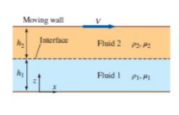
Figure-( 1)
Assume, at the point of wall and fluid, the velocity of the fluid is equal to zero.
Write the expression for velocity of the fluid 1,
Here, the velocity of fluid 1 is
Assume, the velocity of the fluid 2 at the free surface of the wall is equal to the velocity of the moving plates.
Write the expressions for the velocity of fluid 2.
Here, the velocity of fluid 2 is
Write the expression for velocity at interface.
Write the expression for rate of shear stress.
Here, the kinematic coefficient of fluid is
Write the expression for the shear stress acting on fluid 1.
Here, the kinematic coefficient of fluid 1 is
Write the expression for the shear stress acting on fluid 2.
Here, the kinematic coefficient of fluid 2 is
Write the expression for the rate of shear stress at interface.
Write the expression for pressure at the bottom of the flow,
Here, the pressure is
Write the expression for the pressure at the interface of fluid 1.
Here, the pressure at the fluid 1 is
Write the expression for the pressure at the interface of fluid 2.
Here, the pressure at the fluid 1 is
Assume, at the interface of the fluid the pressure cannot have discontinuity and the surface is ignored.
Write the expression for the pressure at interface of fluid.
Conclusion:
The first boundary condition is
The second boundary condition is
The third boundary condition is
The fourth boundary conditions is
The fifth boundary condition is
The sixth boundary condition
is
(b)
The expressions for the velocity of fluid 1 and 2.
Answer to Problem 136P
The expression for the velocity of fluid 1 is
The expression for the velocity of fluid 2 is
Explanation of Solution
Write the expression for
Here, the velocity of flow for fluid 1 is
Write the expression for
Here, the velocity of flow for fluid 2 is
Calculation:
Integrate Equation (XIII) with respect to
Here, the constant is
Integrate Equation (XIII) with respect to
Here, the constant is
Integrate Equation (XIV) with respect to
Here, the constant is
Integrate Equation (XIV) with respect to
Here, the constant is
Substitute
Substitute
Substitute
Substitute
Substitute
Differentiate Equation (XXI) with respect to
Substitute
Substitute
Substitute
Substitute
Conclusion:
The expression for the velocity of fluid 1 is
The expression for the velocity of fluid 2 is
(c)
The expressions for pressure of fluid 1 and 2.
Answer to Problem 136P
The expression for the pressure of fluid 1 is
The expression for the pressure of fluid 2 is
Explanation of Solution
Write the expression for
Here, the density of the fluid 1 is
Write the expression for
Here, the density of the fluid 2 is
Calculation:
Integrate Equation (XXV) with respect to
Here, the constant is
Substitute
Substitute
Integrate Equation (XXVI) with respect to
Here, the constant is
Substitute
Substitute
Substitute
Conclusion:
The expression for the pressure of fluid 1 is
The expression for the pressure of fluid 2 is
(d)
The plot
Answer to Problem 136P
The following Figure-(2) represents the velocities of fluid 1 and 2.

Explanation of Solution
Given information:
The fluid 1 be water and the fluid 2 be unused engine oil, at
The following figure shows that two parallel flat plates.
Write the expression for the velocity of fluid 1.
Here, the distance is
Write the expression for the velocity of fluid 2.
Calculation:
Refer the Table-A-3E, "Properties of saturated water", to obtain the value of dynamic viscosity of water is
Refer the Table-A-7E, "Properties of the atmosphere at high attitude", to obtain the value of dynamic viscosity of unused engine oil is
Substitute
Substitute
The following graph represents the velocities of fluid 1 and 2.
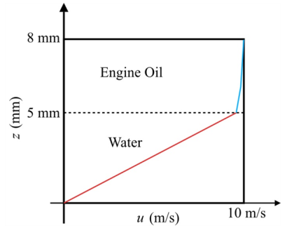
Figure-(2)
In the fluid 1 the linear curve is increasing with respect to the velocity of flow and height of fluid 1. In the fluid 2 the curve is increasing with respect to the velocity of flow and height of fluid 2.
Conclusion:
The following Figure-(2) represents the velocities of fluid 1 and 2.

Want to see more full solutions like this?
Chapter 7 Solutions
FLUID MECHANICS FUND. (LL)-W/ACCESS


- my ID# 016948724. Please solve this problem step by steparrow_forwardMy ID# 016948724 please find the forces for Fx=0: fy=0: fz=0: please help me to solve this problem step by steparrow_forwardMy ID# 016948724 please solve the proble step by step find the forces fx=o: fy=0; fz=0; and find shear moment and the bending moment diagran please draw the diagram for the shear and bending momentarrow_forward
- My ID#016948724 please solve this problems and show me every step clear to follow pleasearrow_forwardMy ID# 016948724arrow_forwardPlease do not use any AI tools to solve this question. I need a fully manual, step-by-step solution with clear explanations, as if it were done by a human tutor. No AI-generated responses, please.arrow_forward
- Please do not use any AI tools to solve this question. I need a fully manual, step-by-step solution with clear explanations, as if it were done by a human tutor. No AI-generated responses, please.arrow_forwardPlease do not use any AI tools to solve this question. I need a fully manual, step-by-step solution with clear explanations, as if it were done by a human tutor. No AI-generated responses, please.arrow_forward[Q2]: The cost information supplied by the cost accountant is as follows:Sales 20,00 units, $ 10 per unitCalculate the (a/ newsale guantity and (b) new selling price to earn the sameVariable cost $ 6 per unit, Fixed Cost $ 30,000, Profit $ 50,000profit ifi) Variable cost increases by $ 2 per unitil) Fixed cost increase by $ 10,000Ili) Variable cost increase by $ 1 per unit and fixed cost reduces by $ 10,000arrow_forward
 Principles of Heat Transfer (Activate Learning wi...Mechanical EngineeringISBN:9781305387102Author:Kreith, Frank; Manglik, Raj M.Publisher:Cengage Learning
 International Edition---engineering Mechanics: St...Mechanical EngineeringISBN:9781305501607Author:Andrew Pytel And Jaan KiusalaasPublisher:CENGAGE L
 Refrigeration and Air Conditioning Technology (Mi...Mechanical EngineeringISBN:9781305578296Author:John Tomczyk, Eugene Silberstein, Bill Whitman, Bill JohnsonPublisher:Cengage Learning