
ENGINEERING MECHANICS: STATICS
14th Edition
ISBN: 9780135681879
Author: HIBBELER
Publisher: PEARSON
expand_more
expand_more
format_list_bulleted
Videos
Textbook Question
Chapter 6.6, Problem 103P
Determine the horizontal and vertical components of force that the pins at A and B exert on the fame.
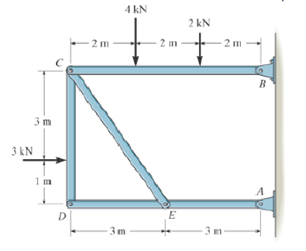
Prob. 6-103
Expert Solution & Answer

Trending nowThis is a popular solution!

Learn your wayIncludes step-by-step video

schedule07:26
Students have asked these similar questions
Solve this problem and show all of the work. Show how the moments are calculated and draw a diagram
Problem:
Textbook Problem 10.52 and 10.53.
Determine the moment of inertia of the area about the x-
axis and the y-axis.
3 in. 3 in.
6 in.
2 in.
4 in.
x
Several reactions are carried out in a closed vessel. The following data are taken for the concentration of compounds A, B, and C [grams per liter] as a function of time [minutes], from the start of the reaction. Show the resulting data and trendlines, with equation and value, on the appropriate graph type (rectilinear, semilog, or log–log) to make the data appear linear.
Chapter 6 Solutions
ENGINEERING MECHANICS: STATICS
Ch. 6.3 - In each case, calculate the support reactions and...Ch. 6.3 - Identify the zero-force members in each truss....Ch. 6.3 - State if the members are in tension or...Ch. 6.3 - State if the members are in tension or...Ch. 6.3 - State if the members are in tension or...Ch. 6.3 - Determine the greatest load P that can be applied...Ch. 6.3 - Identify the zero-force members in the truss....Ch. 6.3 - State if the members are in tension or...Ch. 6.3 - Set P1 = 20 kN, P2 = 10 kN. Probs. 6-1/2Ch. 6.3 - Set P1 = 45 kN, P2 = 30 kN. Probs. 6-1/2
Ch. 6.3 - State if the members are in tension or...Ch. 6.3 - Determine the force in each member of the truss...Ch. 6.3 - Determine the force in each member of the truss,...Ch. 6.3 - Determine the force in each member of the truss,...Ch. 6.3 - Determine the force in each member of the truss...Ch. 6.3 - Determine the force in each member of the truss...Ch. 6.3 - Determine the force in each member of the truss...Ch. 6.3 - Set P1 = 6 kN, P2 = 9 kN. Probs. 6-9/10Ch. 6.3 - Determine the force in each member of the Pratt...Ch. 6.3 - Determine the force in each member of the truss...Ch. 6.3 - Determine the force in each member of the truss in...Ch. 6.3 - Members AB and BC can each support a maximum...Ch. 6.3 - If a = 6 ft, determine the greatest load P the...Ch. 6.3 - State whether the members are in tension or...Ch. 6.3 - If the maximum force that any member can support...Ch. 6.3 - Set P1 = 10 kN, P2 = 8 kN. Probs. 6-18/19Ch. 6.3 - Determine the force in each member of the truss...Ch. 6.3 - Set P1 = 9 kN, P2 = 15 kN. Probs. 6-20/21Ch. 6.3 - Determine the force in each member of the truss...Ch. 6.3 - Determine the force in each member of the double...Ch. 6.3 - Determine the force in each member of the truss in...Ch. 6.3 - Determine the maximum magnitude of load P that can...Ch. 6.3 - Take P = 2 kN. Probs. 6-25/26Ch. 6.3 - Determine the maximum magnitude P of the two loads...Ch. 6.4 - Determine the force in members BC, CF, and FE....Ch. 6.4 - State if the members are in tension or...Ch. 6.4 - State if the members are in tension or...Ch. 6.4 - State if the members are in tension or...Ch. 6.4 - State if the members are in tension or...Ch. 6.4 - State if the members are in tension or...Ch. 6.4 - Determine the force in members DC, HC, and HI of...Ch. 6.4 - Determine the force in members ED, EH, and GH of...Ch. 6.4 - Determine the force in members HG, HE and DE of...Ch. 6.4 - Determine the force in members CD, HI, and CH of...Ch. 6.4 - State if these members are in tension or...Ch. 6.4 - State if these members are in tension or...Ch. 6.4 - Determine the force in members GF, CD, and GC, and...Ch. 6.4 - Determine the force in members GH, BC, and BG of...Ch. 6.4 - Determine the force in members EF, CF, and BC, and...Ch. 6.4 - Determine the force in members AF, BF, and BC, and...Ch. 6.4 - State if these members are in tension or...Ch. 6.4 - Determine the force in members CD, CF, and CG and...Ch. 6.4 - Determine the force developed in members FE, EB,...Ch. 6.4 - Determine the force in members BC, HC, and HG....Ch. 6.4 - Determine the force in members CD, CJ, GJ, and CG...Ch. 6.4 - Determine the force in members BE, EF, and CB, and...Ch. 6.4 - Determine the force in members BF, BG, and AB, and...Ch. 6.4 - Determine the force in members BC, CH, GH, and CG...Ch. 6.4 - Determine the force in members CD, CJ, and KJ and...Ch. 6.4 - Determine the force in members JK, CJ, and CD of...Ch. 6.4 - Determine the force in members HI, FI, and EF of...Ch. 6.6 - In each case, identify any two-force members, and...Ch. 6.6 - Determine the force P needed to hold the 60-lb...Ch. 6.6 - Determine the horizontal and vertical components...Ch. 6.6 - If a 100-N force is applied to the handles of the...Ch. 6.6 - Determine the horizontal and vertical components...Ch. 6.6 - Determine the normal force that the 100-lb plate A...Ch. 6.6 - Also, determine the proper placement x of the hook...Ch. 6.6 - Determine the components of reaction at A and B....Ch. 6.6 - Determine the reactions at D. Prob. F6-20Ch. 6.6 - Determine the components of reaction at A and C....Ch. 6.6 - Determine the components of reaction at C. Prob....Ch. 6.6 - Determine the components of reaction at E. Prob....Ch. 6.6 - Determine the components of reaction at D and the...Ch. 6.6 - Determine the force P required to hold the 100-lb...Ch. 6.6 - The block weighs 100 lb. Prob. 6-62Ch. 6.6 - Determine the force P required to hold the 50-kg...Ch. 6.6 - Determine the force P required to hold the 150-kg...Ch. 6.6 - Determine the horizontal and vertical components...Ch. 6.6 - Determine the horizontal and vertical components...Ch. 6.6 - Also, what are the horizontal and vertical...Ch. 6.6 - Determine the horizontal and vertical components...Ch. 6.6 - Determine the reactions at supports A and B. Prob....Ch. 6.6 - The suspended cylinder has a mass of 75 kg. Prob....Ch. 6.6 - Determine the reactions at the supports A, C, and...Ch. 6.6 - Determine the resultant force at pins A, B, and C...Ch. 6.6 - Determine the reactions at the supports at A, E,...Ch. 6.6 - Determine the horizontal and vertical components...Ch. 6.6 - Determine the horizontal and vertical components...Ch. 6.6 - Determine the horizontal and vertical components...Ch. 6.6 - Determine the horizontal and vertical components...Ch. 6.6 - There is a hinge (pin) at D. Determine the...Ch. 6.6 - Determine the force P exerted on each of the...Ch. 6.6 - The toggle clamp is subjected to a force F at the...Ch. 6.6 - Determine the force the load creates in member DB...Ch. 6.6 - Determine the compressive force developed on the...Ch. 6.6 - Also, find the horizontal and vertical components...Ch. 6.6 - Also, what are the horizontal and vertical...Ch. 6.6 - Determine the force in the guy cable AI and the...Ch. 6.6 - When the walking beam ABC is horizontal, the force...Ch. 6.6 - Determine the force that the jaws J of the metal...Ch. 6.6 - It consists of two toggles ABC and DBF, which are...Ch. 6.6 - The 600-N load is applied to the pin. Prob. 6-89Ch. 6.6 - If the wheel at A exerts a normal force of FA = 80...Ch. 6.6 - The shovel load has a mass of 1.25 Mg and a center...Ch. 6.6 - Determine the horizontal and vertical components...Ch. 6.6 - Determine the compressive force P that is exerted...Ch. 6.6 - If each coin weighs 0.0235 lb, determine the...Ch. 6.6 - Assuming the blades are pin connected at B and the...Ch. 6.6 - Determine the total force he must exert on bar AB...Ch. 6.6 - Determine the total force he must exert on bar AB...Ch. 6.6 - The cable is attached to D, passes over the smooth...Ch. 6.6 - The grip at B on member DAB resists both...Ch. 6.6 - If the compression in the spring is 20 mm when the...Ch. 6.6 - If a clamping force of 300 N is required at A,...Ch. 6.6 - If a force of F = 350 N is applied to the handle...Ch. 6.6 - Determine the horizontal and vertical components...Ch. 6.6 - Determine the force in the hydraulic cylinder AB...Ch. 6.6 - The spring has a stiffness of k = 6 kN/m. Prob....Ch. 6.6 - If d = 0.75 ft and the spring has an unstretched...Ch. 6.6 - If a force of F = 50 lb is applied to the pads at...Ch. 6.6 - If there is a 300-kg stone in the bucket, with...Ch. 6.6 - when the mechanism is in the position shown. The...Ch. 6.6 - Prob. 110PCh. 6.6 - Prob. 111PCh. 6.6 - If the sprig has a stiffness of k = 15 lb/in., and...Ch. 6.6 - Through this arrangement, a small weight can...Ch. 6.6 - Through this arrangement, a small weight can...Ch. 6.6 - If only vertical forces are supported at the...Ch. 6.6 - Determine the force in each member of the truss...Ch. 6.6 - Determine the force in each member of the truss...Ch. 6.6 - Determine the force in member GJ and GC of the...Ch. 6.6 - Determine the force in members GF, FB, and BC of...Ch. 6.6 - Determine the horizontal and vertical components...Ch. 6.6 - Determine the horizontal and vertical components...Ch. 6.6 - Determine the resultant forces at pins B and C on...
Additional Engineering Textbook Solutions
Find more solutions based on key concepts
Give an example of a data constraint.
Database Concepts (8th Edition)
Days in a Month Write a class named MonthDays, The classs constructor should accept two arguments: An integer f...
Starting Out with Java: From Control Structures through Objects (7th Edition) (What's New in Computer Science)
A method in a subclass having the same name as a method in the superclass but a different signature is an examp...
Starting Out with Java: From Control Structures through Data Structures (4th Edition) (What's New in Computer Science)
Determine the slope and deflection of end A of the cantilevered beam. E = 200 GPa and I = 65.0(106) mm4. F121
Mechanics of Materials (10th Edition)
17–1C A high-speed aircraft is cruising in still air. How does the temperature of air at the nose of the aircra...
Thermodynamics: An Engineering Approach
Find the no-load value of υo in the circuit shown.
Find υo when RL is 150 Ω.
How much power is dissipated in th...
Electric Circuits. (11th Edition)
Knowledge Booster


Learn more about
Need a deep-dive on the concept behind this application? Look no further. Learn more about this topic, mechanical-engineering and related others by exploring similar questions and additional content below.Similar questions
- Solve this problem and show all of the workarrow_forwardSolve this problem and show all of the workarrow_forwardThe 4-lbs piece of putty is dropped 12 ft onto the 16-lbs block initially at rest on the two springs, each with a stiffness k = 5 lbs/in. Calculate the additional deflection d of the springs due to the impact of the putty, which adheres to the block upon contact.arrow_forward
- Solve this probem. Draw the diagram and show how the moments are calculated in all of the directionsarrow_forwardSolve this problem and show all of the workarrow_forwardThe 4-lbs piece of putty is dropped 12 ft onto the 16-lbs block initially at rest on the two springs, each with a stiffness k = 5 lbs/in. Calculate the additional deflection d of the springs due to the impact of the putty, which adheres to the block upon contact.arrow_forward
- A converging elbow (see the figure below) turns water through an angle of 135° in a vertical plane. The flow cross section diameter is 400 mm at the elbow inlet, section (1), and 200 mm at the elbow outlet, section (2). The elbow flow passage volume is 0.2 m³ between sections (1) and (2). The water volume flowrate is 0.1 m³/s and the elbow inlet and outlet pressures are 140 kPa and 90 kPa. The elbow mass is 11 kg. Calculate the (a) horizontal (x direction) and (b) vertical (z direction) anchoring forces required to hold the elbow in place. D₂- Section (1)- D₁ = 400 mm 135° 200 mm Section (2) (a) Fx= i 20809.96 N (b) Fz= i -120265 Narrow_forward2: A rectangular aluminum block is loaded uniformly in three directions. The loadings are as follows:a 50 kN total resulting compressive load in the x-direction, a 200 kPa uniformly distributed tensile load in they-direction, and a 0.03 MN total resulting tensile load in the z-direction. The block has the following dimensions:L = 1 m, b = 20 cm, h = 350 mm. Use E = 70 GPa and ν = 0.25.Determine the strain in the x and y axes respectively. For the strain in the y-direction to be equal to 0, how much uniformly distributed load inthe surface of y-direction should be added? (+ for tensile, - for compressive) Answers: 5 -1.122 x10⁻⁵ / 3 decimals 6 5.102 x10⁻⁶ / 3 decimals 7 -0.357 MPa / 3 decimalsarrow_forwardA spherical balloon with a diameter of 9 m is filled with water vapour at 200˚C and 200 kPa. Determine the mass of water in the balloon. The R value for water is 0.4615 kJ/kg∙K.arrow_forward
- Correct answers are written below. Detailed and correct solution only with fbd. I will upvote. 1: A 3 m alloy shaft fixed at one end has a torsional shearing stress capacity of 55 MPa. Due to improper fabrication, its cross-sectionalarea has become irregularly shaped. Its effective polar moment of inertia has become 2 x10⁻⁷ m4, and the maximum torque stress acts at 7.5 cm fromthe center of the shaft.[1]: If the shaft is to be replaced by a properly manufactured solid circular shaft that has a maximumshearing stress capacity of 70 MN/m2, what is the minimum diameter required so it can withstand the sameload? [2]: Calculate the thickness of a hollow circular shaft with the same outside diameter calculated initem [1] that can carry the same load. Limit the maximum shearing stress of the hollow circular shaft to0.09 GPa.Determine the angle of twist on the free end of the shaft. Use G = 150 x103 GPa. [3]: Use the solidcircular shaft from [1] and use the hollow circular shaft from [2].…arrow_forwardtwo closed 1 m3 chambers are filled with fluid at 25˚C and 1 atm. One is filled with pure carbon dioxide and one is filled with pure water. Only considering the weight of the fluids, which chamber is heavier?arrow_forwardCorrect answers are written below. Detailed and correct solution only with fbd. I will upvote. 1: A 3 m alloy shaft fixed at one end has a torsional shearing stress capacity of 55 MPa. Due to improper fabrication, its cross-sectionalarea has become irregularly shaped. Its effective polar moment of inertia has become 2 x10⁻⁷ m4, and the maximum torque stress acts at 7.5 cm fromthe center of the shaft.[1]: If the shaft is to be replaced by a properly manufactured solid circular shaft that has a maximumshearing stress capacity of 70 MN/m2, what is the minimum diameter required so it can withstand the sameload? [2]: Calculate the thickness of a hollow circular shaft with the same outside diameter calculated initem [1] that can carry the same load. Limit the maximum shearing stress of the hollow circular shaft to0.09 GPa.Determine the angle of twist on the free end of the shaft. Use G = 150 x103 GPa. [3]: Use the solidcircular shaft from [1] and use the hollow circular shaft from [2].…arrow_forward
arrow_back_ios
SEE MORE QUESTIONS
arrow_forward_ios
Recommended textbooks for you
 Elements Of ElectromagneticsMechanical EngineeringISBN:9780190698614Author:Sadiku, Matthew N. O.Publisher:Oxford University Press
 Mechanics of Materials (10th Edition)Mechanical EngineeringISBN:9780134319650Author:Russell C. HibbelerPublisher:PEARSON
 Thermodynamics: An Engineering ApproachMechanical EngineeringISBN:9781259822674Author:Yunus A. Cengel Dr., Michael A. BolesPublisher:McGraw-Hill Education
 Control Systems EngineeringMechanical EngineeringISBN:9781118170519Author:Norman S. NisePublisher:WILEY
 Mechanics of Materials (MindTap Course List)Mechanical EngineeringISBN:9781337093347Author:Barry J. Goodno, James M. GerePublisher:Cengage Learning
 Engineering Mechanics: StaticsMechanical EngineeringISBN:9781118807330Author:James L. Meriam, L. G. Kraige, J. N. BoltonPublisher:WILEY
Elements Of Electromagnetics
Mechanical Engineering
ISBN:9780190698614
Author:Sadiku, Matthew N. O.
Publisher:Oxford University Press
Mechanics of Materials (10th Edition)
Mechanical Engineering
ISBN:9780134319650
Author:Russell C. Hibbeler
Publisher:PEARSON
Thermodynamics: An Engineering Approach
Mechanical Engineering
ISBN:9781259822674
Author:Yunus A. Cengel Dr., Michael A. Boles
Publisher:McGraw-Hill Education
Control Systems Engineering
Mechanical Engineering
ISBN:9781118170519
Author:Norman S. Nise
Publisher:WILEY
Mechanics of Materials (MindTap Course List)
Mechanical Engineering
ISBN:9781337093347
Author:Barry J. Goodno, James M. Gere
Publisher:Cengage Learning
Engineering Mechanics: Statics
Mechanical Engineering
ISBN:9781118807330
Author:James L. Meriam, L. G. Kraige, J. N. Bolton
Publisher:WILEY
Physics 33 - Fluid Statics (1 of 10) Pressure in a Fluid; Author: Michel van Biezen;https://www.youtube.com/watch?v=mzjlAla3H1Q;License: Standard YouTube License, CC-BY