EBK VECTOR MECHANICS FOR ENGINEERS: STA
12th Edition
ISBN: 8220106797068
Author: BEER
Publisher: YUZU
expand_more
expand_more
format_list_bulleted
Concept explainers
Videos
Textbook Question
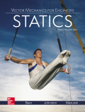
Chapter 6.4, Problem 6.126P
Solve Prob. 6.125 when (a) β = 0, (b) β = 6.
Fig. P6.125
Expert Solution & Answer
Want to see the full answer?
Check out a sample textbook solution
Students have asked these similar questions
I need help with a MATLAB code. This code just keeps running and does not give me any plots. I even reduced the tolerance from 1e-9 to 1e-6. Can you help me fix this? Please make sure your solution runs.
% Initial Conditions
rev = 0:0.001:2;
g1 = deg2rad(1);
g2 = deg2rad(3);
g3 = deg2rad(6);
g4 = deg2rad(30);
g0 = deg2rad(0);
Z0 = 0;
w0 = [0; Z0*cos(g0); -Z0*sin(g0)];
Z1 = 5;
w1 = [0; Z1*cos(g1); -Z1*sin(g1)];
Z2 = 11;
w2 = [0; Z2*cos(g2); -Z2*sin(g2)];
[v3, psi3, eta3] = Nut_angle(Z2, g2, w2);
plot(v3, psi3)
function dwedt = K_DDE(~, w_en)
% Extracting the initial condtions to a variable
% Extracting the initial condtions to a variable
w = w_en(1:3);
e = w_en(4:7);
Z = w_en(8);
I = 0.060214;
J = 0.015707;
x = (J/I) - 1;
y = Z - 1;
s = Z;
% Kinematic Differential Equations
dedt = zeros(4,1);
dedt(1) = pi*(e(3)*(s-w(2)-1) + e(2)*w(3) + e(4)*w(1));
dedt(2) = pi*(e(4)*(w(2)-1-s) + e(3)*w(1) - e(1)*w(3));
dedt(3) = pi*(-e(1)*(s-w(2)-1) - e(2)*w(1) + e(4)*w(3));…
alpha 1 is not zero
alpha 1 can equal alpha 2
use velocity triangle to solve for alpha 1
USE MATLAB ONLY
provide typed code
solve for velocity triangle and dont provide copied answer
Turbomachienery .
GIven:
vx = 185 m/s, flow angle = 60 degrees, (leaving a stator in axial flow) R = 0.5, U = 150 m/s, b2 = -a3, a2 = -b3
Find: velocity triangle , a. magnitude of abs vel leaving rotor (m/s) b. flow absolute angles (a1, a2, a3) 3. flow rel angles (b2, b3) d. specific work done e. use code to draw vel. diagram
Use this code for plot
% plots Velocity Tri. in Ch4
function plotveltri(al1,al2,al3,b2,b3)
S1L = [0 1];
V1x = [0 0];
V1s = [0 1*tand(al3)];
S2L = [2 3];
V2x = [0 0];
V2s = [0 1*tand(al2)];
W2s = [0 1*tand(b2)];
U2x = [3 3];
U2y = [1*tand(b2) 1*tand(al2)];
S3L = [4 5];
V3x = [0 0];
V3r = [0 1*tand(al3)];
W3r = [0 1*tand(b3)];
U3x = [5 5];
U3y = [1*tand(b3) 1*tand(al3)];
plot(S1L,V1x,'k',S1L,V1s,'r',...
S2L,V2x,'k',S2L,V2s,'r',S2L,W2s,'b',U2x,U2y,'g',...…
3. Find a basis of eigenvectors and diagonalize.
4
0
-19
7
a.
b.
1-42
16
12-20
[21-61
Chapter 6 Solutions
EBK VECTOR MECHANICS FOR ENGINEERS: STA
Ch. 6.1 - Using the method of joints, determine the force in...Ch. 6.1 - Using the method of joints, determine the force in...Ch. 6.1 - Using the method of joints, determine the force in...Ch. 6.1 - Using the method of joints, determine the force in...Ch. 6.1 - Using the method of joints, determine the force in...Ch. 6.1 - Using the method of joints, determine the force in...Ch. 6.1 - Using the method of joints, determine the force in...Ch. 6.1 - Using the method of joints, determine the force in...Ch. 6.1 - Using the method of joints, determine the force in...Ch. 6.1 - Determine the force in each member of the truss...
Ch. 6.1 - Determine the force in each member of the Gambrel...Ch. 6.1 - Determine the force in each member of the Howe...Ch. 6.1 - Using the method of joints, determine the force in...Ch. 6.1 - Prob. 6.14PCh. 6.1 - Determine the force in each member of the Warren...Ch. 6.1 - Solve Problem 6.15 assuming that the load applied...Ch. 6.1 - Determine the force in each member of the Pratt...Ch. 6.1 - The truss shown is one of several supporting an...Ch. 6.1 - Determine the force in each member of the Pratt...Ch. 6.1 - Solve Problem 6.19 assuming that the load applied...Ch. 6.1 - Determine the force in each of the members located...Ch. 6.1 - Determine the force in member DE and in each of...Ch. 6.1 - Determine the force in each of the members located...Ch. 6.1 - The portion of truss shown represents the upper...Ch. 6.1 - For the tower and loading of Prob. 6.24 and...Ch. 6.1 - Solve Problem 6.24 assuming that the cables...Ch. 6.1 - Determine the force in each member of the truss...Ch. 6.1 - Determine the force in each member of the truss...Ch. 6.1 - Determine whether the trusses of Problems 6.31a,...Ch. 6.1 - Determine whether the trusses of Problems 6.31b,...Ch. 6.1 - For the given loading, determine the zero-force...Ch. 6.1 - For the given loading, determine the zero-force...Ch. 6.1 - For the given loading, determine the zero-force...Ch. 6.1 - Determine the zero-force members in the truss of...Ch. 6.1 - The truss shown consists of six members and is...Ch. 6.1 - The truss shown consists of six members and is...Ch. 6.1 - The truss shown consists of six members and is...Ch. 6.1 - Prob. 6.38PCh. 6.1 - The truss shown consists of nine members and is...Ch. 6.1 - Solve Prob. 6.39 for P = 0 and Q = (900 N)k. 6.39...Ch. 6.1 - The truss shown consists of 18 members and is...Ch. 6.1 - The truss shown consists of 18 members and is...Ch. 6.2 - Determine the force in members BD and DE of the...Ch. 6.2 - Determine the force in members DG and EG of the...Ch. 6.2 - Determine the force in members BD and CD of the...Ch. 6.2 - Determine the force in members DF and DG of the...Ch. 6.2 - A floor truss is loaded as shown. Determine the...Ch. 6.2 - A floor truss is loaded as shown. Determine the...Ch. 6.2 - Determine the force in members CD and DF of the...Ch. 6.2 - Determine the force in members CE and EF of the...Ch. 6.2 - Determine the force in members DE and DF of the...Ch. 6.2 - Determine the force in members EG and EF of the...Ch. 6.2 - Determine the force in members DF and DE of the...Ch. 6.2 - Determine the force in members CD and CE of the...Ch. 6.2 - A Pratt roof truss is loaded as shown. Determine...Ch. 6.2 - A Pratt roof truss is loaded as shown. Determine...Ch. 6.2 - A Howe scissors roof truss is loaded as shown....Ch. 6.2 - A Howe scissors roof truss is loaded as shown....Ch. 6.2 - Determine the force in members AD, CD, and CE of...Ch. 6.2 - Determine the force in members DG, FG, and FH of...Ch. 6.2 - Determine the force in member GJ of the truss...Ch. 6.2 - Determine the force in members DG and FH of the...Ch. 6.2 - Prob. 6.63PCh. 6.2 - Prob. 6.64PCh. 6.2 - The diagonal members in the center panels of the...Ch. 6.2 - The diagonal members in the center panels of the...Ch. 6.2 - The diagonal members in the center panels of the...Ch. 6.2 - Solve Prob. 6.67 assuming that the 9-kip load has...Ch. 6.2 - Classify each of the structures shown as...Ch. 6.2 - Classify each of the structures shown as...Ch. 6.2 - 6.70 through 6.74 classify as determinate or...Ch. 6.2 - 6.70 through 6.74 classify as determinate or...Ch. 6.2 - 6.70 through 6.74 classify as determinate or...Ch. 6.2 - 6.70 through 6.74 classify as determinate or...Ch. 6.3 - For the frame and loading shown, draw the...Ch. 6.3 - For the frame and loading shown, draw the...Ch. 6.3 - Draw the free-body diagram(s) needed to determine...Ch. 6.3 - Knowing that the pulley has a radius of 0.5 m,...Ch. 6.3 - and 6.76 Determine the force in member BD and the...Ch. 6.3 - Prob. 6.76PCh. 6.3 - For the frame and loading shown, determine the...Ch. 6.3 - Determine the components of all forces acting on...Ch. 6.3 - The hydraulic cylinder CF, which partially...Ch. 6.3 - The hydraulic cylinder CF, which partially...Ch. 6.3 - Determine the components of all forces acting on...Ch. 6.3 - Determine the components of all forces acting on...Ch. 6.3 - Determine the components of the reactions at A and...Ch. 6.3 - Determine the components of the reactions at D and...Ch. 6.3 - Determine the components of the reactions at A and...Ch. 6.3 - Determine the components of the reactions at A and...Ch. 6.3 - Determine the components of the reactions at A and...Ch. 6.3 - The 48-lb load can be moved along the line of...Ch. 6.3 - The 48-lb load is removed and a 288-lb in....Ch. 6.3 - (a) Show that, when a frame supports a pulley at...Ch. 6.3 - Knowing that each pulley has a radius of 250 mm,...Ch. 6.3 - Knowing that the pulley has a radius of 75 mm,...Ch. 6.3 - Prob. 6.93PCh. 6.3 - Prob. 6.94PCh. 6.3 - A trailer weighing 2400 lb is attached to a...Ch. 6.3 - In order to obtain a better weight distribution...Ch. 6.3 - The cab and motor units of the front-end loader...Ch. 6.3 - Solve Problem 6.97 assuming that the 75-kN load...Ch. 6.3 - Knowing that P = 90 lb and Q = 60 lb, determine...Ch. 6.3 - Knowing that P = 90 lb and Q = 60 lb, determine...Ch. 6.3 - For the frame and loading shown, determine the...Ch. 6.3 - For the frame and loading shown, determine the...Ch. 6.3 - Prob. 6.103PCh. 6.3 - Prob. 6.104PCh. 6.3 - For the frame and loading shown, determine the...Ch. 6.3 - Solve Prob. 6.105 assuming that the 6-kN load has...Ch. 6.3 - The axis of the three-hinge arch ABC is a parabola...Ch. 6.3 - The axis of the three-hinge arch ABC is a parabola...Ch. 6.3 - 6.109 and 6.110 Neglecting the effect of friction...Ch. 6.3 - and 6.110 Neglecting the effect of friction at the...Ch. 6.3 - 6.111, 6.112, and 6.113 Members ABC and CDE are...Ch. 6.3 - 6.111, 6.112, and 6.113 Members ABC and CDE are...Ch. 6.3 - 6.111, 6.112, and 6.113 Members ABC and CDE are...Ch. 6.3 - Members ABC and CDE are pin-connected at C and...Ch. 6.3 - Solve Prob. 6.112 assuming that the force P is...Ch. 6.3 - Solve Prob. 6.114 assuming that the force P is...Ch. 6.3 - Four beams, each with a length of 2a, are nailed...Ch. 6.3 - Four beams, each with a length of 3a, are held...Ch. 6.3 - 6.119 through 6.121 Each of the frames shown...Ch. 6.3 - 6.119 through 6.121 Each of the frames shown...Ch. 6.3 - 6.119 through 6.121 Each of the frames shown...Ch. 6.4 - An 84-lb force is applied to the toggle vise at C....Ch. 6.4 - For the system and loading shown, draw the...Ch. 6.4 - A small barrel weighing 60 lb is lifted by a pair...Ch. 6.4 - The position of member ABC is controlled by the...Ch. 6.4 - The shear shown is used to cut and trim...Ch. 6.4 - A 100-lb force directed vertically downward is...Ch. 6.4 - Prob. 6.124PCh. 6.4 - The control rod CE passes through a horizontal...Ch. 6.4 - Solve Prob. 6.125 when (a) = 0, (b) = 6. Fig....Ch. 6.4 - The press shown is used to emboss a small seal at...Ch. 6.4 - The press shown is used to emboss a small seal at...Ch. 6.4 - The pin at B is attached to member ABC and can...Ch. 6.4 - The pin at B is attached to member ABC and can...Ch. 6.4 - Arm ABC is connected by pins to a collar at B and...Ch. 6.4 - Arm ABC is connected by pins to a collar at B and...Ch. 6.4 - The Whitworth mechanism shown is used to produce a...Ch. 6.4 - Solve Prob. 6.133 when (a) = 60, (b) = 90. Fig....Ch. 6.4 - and 6.136 Two rods are connected by a slider block...Ch. 6.4 - and 6.136 Two rods are connected by a slider block...Ch. 6.4 - 6.137 and 6.138 Rod CD is attached to the collar D...Ch. 6.4 - 6.137 and 6.138 Rod CD is attached to the collar D...Ch. 6.4 - Two hydraulic cylinders control the position of...Ch. 6.4 - Two hydraulic cylinders control the position of...Ch. 6.4 - A steel ingot weighing 8000 lb is lifted by a pair...Ch. 6.4 - If the toggle shown is added to the tongs of Prob....Ch. 6.4 - A 9-m length of railroad rail of mass 40 kg/m is...Ch. 6.4 - The gear-pulling assembly shown consists of a...Ch. 6.4 - The pliers shown are used to grip a...Ch. 6.4 - Prob. 6.146PCh. 6.4 - In using the bolt cutter shown, a worker applies...Ch. 6.4 - The upper blade and lower handle of the...Ch. 6.4 - and 6.150 Determine the force P that must be...Ch. 6.4 - and 6.150 Determine the force P that must be...Ch. 6.4 - Because the brace shown must remain in position...Ch. 6.4 - The specialized plumbing wrench shown is used in...Ch. 6.4 - Prob. 6.153PCh. 6.4 - For the frame and loading shown, determine the...Ch. 6.4 - The telescoping arm ABC is used to provide an...Ch. 6.4 - The telescoping arm ABC of Prob. 6.155 can be...Ch. 6.4 - The motion of the backhoe bucket shown is...Ch. 6.4 - Solve Prob. 6.157 assuming that the 2-kip force P...Ch. 6.4 - The gears A and D are rigidly attached to...Ch. 6.4 - In the planetary gear system shown, the radius of...Ch. 6.4 - Two shafts AC and CF, which lie in the vertical xy...Ch. 6.4 - Two shafts AC and CF, which lie in the vertical xy...Ch. 6.4 - The large mechanical tongs shown are used to grab...Ch. 6 - Using the method of joints, determine the force in...Ch. 6 - Using the method of joints, determine the force in...Ch. 6 - A stadium roof truss is loaded as shown. Determine...Ch. 6 - A stadium roof truss is loaded as shown. Determine...Ch. 6 - Determine the components of all forces acting on...Ch. 6 - Determine the components of the reactions at A and...Ch. 6 - Knowing that the pulley has a radius of 50 mm,...Ch. 6 - For the frame and loading shown, determine the...Ch. 6 - For the frame and loading shown, determine the...Ch. 6 - Water pressure in the supply system exerts a...Ch. 6 - A couple M with a magnitude of 1.5 kNm is applied...Ch. 6 - The compound-lever pruning shears shown can be...
Knowledge Booster


Learn more about
Need a deep-dive on the concept behind this application? Look no further. Learn more about this topic, mechanical-engineering and related others by exploring similar questions and additional content below.Similar questions
- 2. Find the eigenvalues. Find the corresponding eigenvectors. 6 2 -21 [0 -3 1 3 31 a. 2 5 0 b. 3 0 -6 C. 1 1 0 -2 0 7 L6 6 0 1 1 2. (Hint: λ = = 3)arrow_forwardUSE MATLAB ONLY provide typed code solve for velocity triangle and dont provide copied answer Turbomachienery . GIven: vx = 185 m/s, flow angle = 60 degrees, (leaving a stator in axial flow) R = 0.5, U = 150 m/s, b2 = -a3, a2 = -b3 Find: velocity triangle , a. magnitude of abs vel leaving rotor (m/s) b. flow absolute angles (a1, a2, a3) 3. flow rel angles (b2, b3) d. specific work done e. use code to draw vel. diagram Use this code for plot % plots Velocity Tri. in Ch4 function plotveltri(al1,al2,al3,b2,b3) S1L = [0 1]; V1x = [0 0]; V1s = [0 1*tand(al3)]; S2L = [2 3]; V2x = [0 0]; V2s = [0 1*tand(al2)]; W2s = [0 1*tand(b2)]; U2x = [3 3]; U2y = [1*tand(b2) 1*tand(al2)]; S3L = [4 5]; V3x = [0 0]; V3r = [0 1*tand(al3)]; W3r = [0 1*tand(b3)]; U3x = [5 5]; U3y = [1*tand(b3) 1*tand(al3)]; plot(S1L,V1x,'k',S1L,V1s,'r',... S2L,V2x,'k',S2L,V2s,'r',S2L,W2s,'b',U2x,U2y,'g',... S3L,V3x,'k',S3L,V3r,'r',S3L,W3r,'b',U3x,U3y,'g',...... 'LineWidth',2,'MarkerSize',10),...…arrow_forwardUSE MATLAB ONLY provide typed code solve for velocity triangle and dont provide copied answer Turbomachienery . GIven: vx = 185 m/s, flow angle = 60 degrees, R = 0.5, U = 150 m/s, b2 = -a3, a2 = -b3 Find: velocity triangle , a. magnitude of abs vel leaving rotor (m/s) b. flow absolute angles (a1, a2, a3) 3. flow rel angles (b2, b3) d. specific work done e. use code to draw vel. diagram Use this code for plot % plots Velocity Tri. in Ch4 function plotveltri(al1,al2,al3,b2,b3) S1L = [0 1]; V1x = [0 0]; V1s = [0 1*tand(al3)]; S2L = [2 3]; V2x = [0 0]; V2s = [0 1*tand(al2)]; W2s = [0 1*tand(b2)]; U2x = [3 3]; U2y = [1*tand(b2) 1*tand(al2)]; S3L = [4 5]; V3x = [0 0]; V3r = [0 1*tand(al3)]; W3r = [0 1*tand(b3)]; U3x = [5 5]; U3y = [1*tand(b3) 1*tand(al3)]; plot(S1L,V1x,'k',S1L,V1s,'r',... S2L,V2x,'k',S2L,V2s,'r',S2L,W2s,'b',U2x,U2y,'g',... S3L,V3x,'k',S3L,V3r,'r',S3L,W3r,'b',U3x,U3y,'g',...... 'LineWidth',2,'MarkerSize',10),... axis([-1 6 -4 4]), ...…arrow_forward
- The answer should equal to 1157. Please sent me the solution. Thank you!arrow_forwardBONUS: If the volume of the 8cm x 6.5cm x 6cm Block of Aluminum was 312cm3 before machining, find how much material was removed when the fixture below was machined. +2 2.00 cm 6.00 cm 2.50 cm 6.50 cm 1.00 cm 2.50 cm 11.00 cm 8.00 cm 30 CP 9411 FL.4) (m² 1157 Area of triangle = 1/2*B*H Area of circle = лR² Circumference of a circle = 2πR 6.00 cm 6.50 cm 1.50 cm Radius 1.50 cm 1.00 cmarrow_forwardConsider a 5m by 5m wet concret patio with an average water film thickness of .2mm. Now wind at 50 km/h is blowing over the surface. If the air is at 1 atm, 15oC and 35 percent relative humidity, determine how long it will take for the patio to completely dry.arrow_forward
- 70. Compute the number of cubic centimeters of iron required for the cast-iron plate shown. The plate is 3.50 centimeters thick. Round the answer to the nearest cubic centimeter. 50.0 cm 40.0 cm Radius 150° 115.0 cm- 81.0 cmarrow_forwardLaw of Sines Solve the following problems using the Law of Sin 7. Find side x. All dimensions are in inches. -°-67°-37° 81° x Sin A 8.820 X 67°00' 32°00' a sin A b C sin B sin Carrow_forward35. a. Determine B. b. Determine side b. c. Determine side c. 5.330 in.- ZB 73°30'arrow_forward
- Consider a 12 cm internal diameter, 14 m long circular duct whose interior surface is wet. The duct is to be dried by forcing dry air at 1 atm and 15 degrees C throught it at an average velocity of 3m/s. The duct passes through a chilled roo, and it remains at an average temp of 15 degrees C at all time. Determine the mass transfer coeeficient in the duct.arrow_forwardnote n=number of link(dont include the ground link (fixed))arrow_forward6.(单选题) The DOF of the following mechanism is E A F=3x4-2x5-0=2 B F=3x3-2x4-0=1 F=3x3-2x3-2=1 D F=3x4-2x5-1=1arrow_forward
arrow_back_ios
SEE MORE QUESTIONS
arrow_forward_ios
Recommended textbooks for you
 Elements Of ElectromagneticsMechanical EngineeringISBN:9780190698614Author:Sadiku, Matthew N. O.Publisher:Oxford University Press
 Mechanics of Materials (10th Edition)Mechanical EngineeringISBN:9780134319650Author:Russell C. HibbelerPublisher:PEARSON
 Thermodynamics: An Engineering ApproachMechanical EngineeringISBN:9781259822674Author:Yunus A. Cengel Dr., Michael A. BolesPublisher:McGraw-Hill Education
 Control Systems EngineeringMechanical EngineeringISBN:9781118170519Author:Norman S. NisePublisher:WILEY
 Mechanics of Materials (MindTap Course List)Mechanical EngineeringISBN:9781337093347Author:Barry J. Goodno, James M. GerePublisher:Cengage Learning
 Engineering Mechanics: StaticsMechanical EngineeringISBN:9781118807330Author:James L. Meriam, L. G. Kraige, J. N. BoltonPublisher:WILEY
Elements Of Electromagnetics
Mechanical Engineering
ISBN:9780190698614
Author:Sadiku, Matthew N. O.
Publisher:Oxford University Press
Mechanics of Materials (10th Edition)
Mechanical Engineering
ISBN:9780134319650
Author:Russell C. Hibbeler
Publisher:PEARSON
Thermodynamics: An Engineering Approach
Mechanical Engineering
ISBN:9781259822674
Author:Yunus A. Cengel Dr., Michael A. Boles
Publisher:McGraw-Hill Education
Control Systems Engineering
Mechanical Engineering
ISBN:9781118170519
Author:Norman S. Nise
Publisher:WILEY
Mechanics of Materials (MindTap Course List)
Mechanical Engineering
ISBN:9781337093347
Author:Barry J. Goodno, James M. Gere
Publisher:Cengage Learning
Engineering Mechanics: Statics
Mechanical Engineering
ISBN:9781118807330
Author:James L. Meriam, L. G. Kraige, J. N. Bolton
Publisher:WILEY
Dynamics - Lesson 1: Introduction and Constant Acceleration Equations; Author: Jeff Hanson;https://www.youtube.com/watch?v=7aMiZ3b0Ieg;License: Standard YouTube License, CC-BY