
Fundamentals of Applied Electromagnetics (7th Edition)
7th Edition
ISBN: 9780133356816
Author: Fawwaz T. Ulaby, Umberto Ravaioli
Publisher: PEARSON
expand_more
expand_more
format_list_bulleted
Concept explainers
Videos
Textbook Question
Chapter 6.4, Problem 4CQ
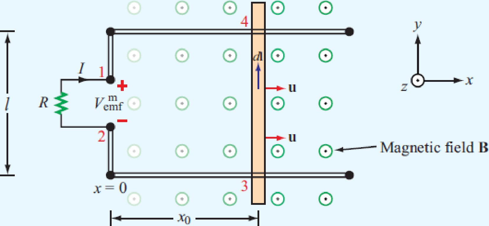
Suppose that no friction is involved in sliding the conducting bar of Fig. 6-8 and that the horizontal arms of the circuit are very long. Hence, if the bar is given an initial push, it should continue moving at a constant velocity, and its movement generates electrical energy in the form of an induced emf, indefinitely. Is this a valid argument? If not, why not? Can we generate electrical energy without having to supply an equal amount of energy by other means?
Expert Solution & Answer
Want to see the full answer?
Check out a sample textbook solution
Students have asked these similar questions
Q3/A unity-feedback system with the forward transfer function
G(S)=
K
S(S+7)
is operating with a closed-loop step response that has 15% overshoot. Do the following:
a. Evaluate the steady-state error for a unit ramp input.
b. Design a lag compensator to improve the steady-state error by a factor of 20 to get a
new dominant closed-loop poles S-3.4+ j5.63. place the pole of the lag compensator
at s=-0.01
c. Design a lag compensator using OP amp if R1= 100KS2 R2=10 KS2 and R3= 10K
please explain and draw the graphs clearly, I am most confused with the graphs thanks
please show step by step and explain clearly
Chapter 6 Solutions
Fundamentals of Applied Electromagnetics (7th Edition)
Ch. 6.2 - Explain Faradays law and the function of Lenzs...Ch. 6.2 - Prob. 2CQCh. 6.2 - Prob. 3CQCh. 6.2 - For the loop shown in Fig. 6-3, what is Vemftr if...Ch. 6.2 - Suppose that the loop of Example 6-1 is replaced...Ch. 6.4 - Suppose that no friction is involved in sliding...Ch. 6.4 - Is the current flowing in the rod of Fig. 6-10 a...Ch. 6.4 - For the moving loop of Fig. 6-9, find I when the...Ch. 6.4 - Suppose that we turn the loop of Fig. 6-9 so that...Ch. 6.5 - Contrast the operation of an ac motor with that of...
Ch. 6.5 - Prob. 7CQCh. 6.5 - Prob. 8CQCh. 6.7 - A poor conductor is characterized by a...Ch. 6.8 - When conduction current flows through a material,...Ch. 6.8 - Verify that the integral form of Ampres law given...Ch. 6.10 - Explain how the charge continuity equation leads...Ch. 6.10 - How long is the relaxation time constant for...Ch. 6.10 - Determine (a) the relaxation time constant and (b)...Ch. 6.11 - Prob. 7ECh. 6 - The switch in the bottom loop of Fig. P6.1 is...Ch. 6 - The loop in Fig. P6.2 is in the xy plane and B =...Ch. 6 - A coil consists of 100 turns of wire wrapped...Ch. 6 - A stationary conducting loop with an internal...Ch. 6 - A circular-loop TV antenna with 0.02 m2 area is in...Ch. 6 - The square loop shown in Fig. P6.6 is coplanar...Ch. 6 - The rectangular conducting loop shown in Fig. P6.7...Ch. 6 - Prob. 8PCh. 6 - Prob. 9PCh. 6 - A 50 cm long metal rod rotates about the z axis at...Ch. 6 - The loop shown in P6.11 moves away from a wire...Ch. 6 - The electromagnetic generator shown in Fig. 6-12...Ch. 6 - The circular, conducting, disk shown in Fig. P6.13...Ch. 6 - The plates of a parallel-plate capacitor have...Ch. 6 - A coaxial capacitor of length l = 6 cm uses an...Ch. 6 - The parallel-plate capacitor shown in Fig. P6.16...Ch. 6 - In wet soil, characterized by = 102 (S/m), r = 1,...Ch. 6 - An electromagnetic wave propagating in seawater...Ch. 6 - At t = 0, charge density v0 was introduced into...Ch. 6 - If the current density in a conducting medium is...Ch. 6 - Prob. 21PCh. 6 - If we were to characterize how good a material is...Ch. 6 - The electric field of an electromagnetic wave...Ch. 6 - The magnetic field in a dielectric material with ...Ch. 6 - Given an electric field E=xE0sinaycos(tkz), where...Ch. 6 - The electric field radiated by a short dipole...Ch. 6 - A Hertzian dipole is a short conducting wire...Ch. 6 - In free space, the magnetic field is given by...Ch. 6 - The magnetic field in a given dielectric medium is...
Knowledge Booster


Learn more about
Need a deep-dive on the concept behind this application? Look no further. Learn more about this topic, electrical-engineering and related others by exploring similar questions and additional content below.Similar questions
- Please solve this question step by step handwritten solution and do not use ai or chat gpt please thank youarrow_forwardFind the mathematical expression in fourier series for this output below shown in the image. This must have the terms ao, ak and bkarrow_forwardPlease solve this question step by step handwritten solution and do not use ai or chat gpt please thank youarrow_forward
- Please solve this question step by step hand written solution and do not use ai or chat gpt thank youarrow_forwardPlease solve this question handwritten, step by step showing details and no ai or chat gpt solution please thank youarrow_forwardPlease explain each quations, I'll give positive feedback. For the graphs, please draw what it looks likearrow_forward
- please explain all steps and draw any drawings, don't just explain what they look like please. thank youarrow_forwardplease explain and show all steps, thank you.arrow_forwardA rectangular waveguide with dimensions a = 2.5 cm, b = 1 cm is to operate at 15 GHz. σ = 0, E4, μ= 1 3- Calculate phase constant for TE10 mode. 4- Calculate the phase velocity and wave impedance for the same mode.arrow_forward
- Find v(t) for t> 0 in the circuit of Fig. below. Assume the switch has been open for a long time and is closed at t = 0. Calculate v (t) at t = 0.5. 10 V 202 www +21 t=0 60 ww 13 F بلا SVarrow_forwardQ: A rectangular waveguide with dimensions a = 2.5 cm, b = 1 cm is to operate at 15 GHz. σ = 0, E4, μ = 1 1- At which frequencies this type of TL (transmission line) operate ? 2- Why this this type is used in such frequencies? 3- Calculate phase constant for TE10 mode. 4- Calculate the phase velocity and wave impedance for the same mode.arrow_forwardK Q1/ For the system G(s)= (s+2)(s+4)(s+5) H(s)=1 a. Draw the Bode log-magnitude and phase plots. b. Find the range of K for stability from your Bode plots. c. Evaluate gain margin, phase margin, zero dB frequency, and 180° frequency from your Bode plots for K = 200arrow_forward
arrow_back_ios
SEE MORE QUESTIONS
arrow_forward_ios
Recommended textbooks for you
 Introductory Circuit Analysis (13th Edition)Electrical EngineeringISBN:9780133923605Author:Robert L. BoylestadPublisher:PEARSON
 Delmar's Standard Textbook Of ElectricityElectrical EngineeringISBN:9781337900348Author:Stephen L. HermanPublisher:Cengage Learning
 Programmable Logic ControllersElectrical EngineeringISBN:9780073373843Author:Frank D. PetruzellaPublisher:McGraw-Hill Education
 Fundamentals of Electric CircuitsElectrical EngineeringISBN:9780078028229Author:Charles K Alexander, Matthew SadikuPublisher:McGraw-Hill Education
 Electric Circuits. (11th Edition)Electrical EngineeringISBN:9780134746968Author:James W. Nilsson, Susan RiedelPublisher:PEARSON
 Engineering ElectromagneticsElectrical EngineeringISBN:9780078028151Author:Hayt, William H. (william Hart), Jr, BUCK, John A.Publisher:Mcgraw-hill Education,
Introductory Circuit Analysis (13th Edition)
Electrical Engineering
ISBN:9780133923605
Author:Robert L. Boylestad
Publisher:PEARSON
Delmar's Standard Textbook Of Electricity
Electrical Engineering
ISBN:9781337900348
Author:Stephen L. Herman
Publisher:Cengage Learning
Programmable Logic Controllers
Electrical Engineering
ISBN:9780073373843
Author:Frank D. Petruzella
Publisher:McGraw-Hill Education
Fundamentals of Electric Circuits
Electrical Engineering
ISBN:9780078028229
Author:Charles K Alexander, Matthew Sadiku
Publisher:McGraw-Hill Education
Electric Circuits. (11th Edition)
Electrical Engineering
ISBN:9780134746968
Author:James W. Nilsson, Susan Riedel
Publisher:PEARSON
Engineering Electromagnetics
Electrical Engineering
ISBN:9780078028151
Author:Hayt, William H. (william Hart), Jr, BUCK, John A.
Publisher:Mcgraw-hill Education,
Introduction to Coulomb's Law or the Electric Force; Author: Flipping Physics;https://www.youtube.com/watch?v=4ubqby1Id4g;License: Standard YouTube License, CC-BY