
Engineering Mechanics: Statics and Study Pack (13th Edition)
13th Edition
ISBN: 9780133027990
Author: Russell C. Hibbeler
Publisher: Prentice Hall
expand_more
expand_more
format_list_bulleted
Concept explainers
Videos
Textbook Question
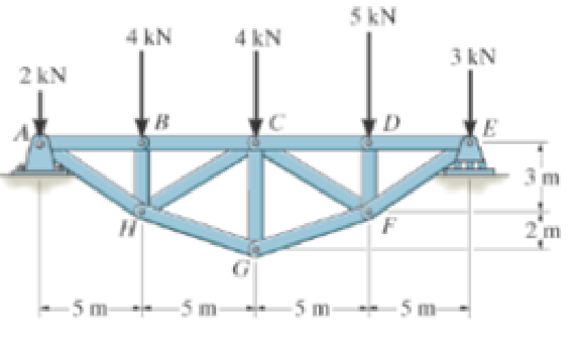
Chapter 6.4, Problem 36P
Determine the force in members CD, CF, and CG and state if these members are in tension or compression.
Probs. 6-39/40
Expert Solution & Answer

Learn your wayIncludes step-by-step video

schedule10:05
Students have asked these similar questions
Page
11-68. The rectangular plate shown is subjected to a uniaxial
stress of 2000 psi. Compute the shear stress and the tensile
developed on a plane forming an angle of 30° with the longitud
axis of the member. (Hint: Assume a cross-sectional area of unity)
2000 psi
2000 psi
hp
11-70. A shear stress (pure shear) of 5000 psi exists on an element.
(a) Determine the maximum tensile and compressive stresses
caused in the element due to this shear.
(b) Sketch the element showing the planes on which the
maximum tensile and compressive stresses act.
11-20. An aluminum specimen of circular cross section, 0.50 in.
in diameter, ruptured under a tensile load of 12,000 lb. The plane
of failure was found to be at 48° with a plane perpendicular to the
longitudinal axis of the specimen.
(a) Compute the shear stress on the failure plane.
(b) Compute the maximum tensile stress.
(c) Compute the tensile stress on the failure plane.
hp
Chapter 6 Solutions
Engineering Mechanics: Statics and Study Pack (13th Edition)
Ch. 6.3 - State if the members are in tension or...Ch. 6.3 - State if the members are in tension or...Ch. 6.3 - Prob. 3FPCh. 6.3 - Determine the greatest load P that can be applied...Ch. 6.3 - Identify the zero-force members in the truss....Ch. 6.3 - State if the members are in tension or...Ch. 6.3 - Prob. 1PCh. 6.3 - Prob. 2PCh. 6.3 - Determine the force in each member of the truss,...Ch. 6.3 - Determine the force in each member of the truss,...
Ch. 6.3 - Prob. 5PCh. 6.3 - Determine the force in each member of the truss...Ch. 6.3 - Determine the force in each member of the Pratt...Ch. 6.3 - Prob. 8PCh. 6.3 - Prob. 9PCh. 6.3 - Prob. 10PCh. 6.3 - Determine the force in each member of the truss...Ch. 6.3 - Prob. 12PCh. 6.3 - Prob. 13PCh. 6.3 - Prob. 14PCh. 6.3 - Prob. 15PCh. 6.3 - State whether the members are in tension or...Ch. 6.3 - If the maximum force that any member can support...Ch. 6.3 - Prob. 18PCh. 6.3 - Prob. 19PCh. 6.3 - Prob. 20PCh. 6.3 - Prob. 21PCh. 6.3 - Determine the force in each member of the double...Ch. 6.3 - Prob. 23PCh. 6.3 - Prob. 24PCh. 6.3 - Prob. 25PCh. 6.3 - Prob. 26PCh. 6.4 - Determine the force in members BC, CF, and FE....Ch. 6.4 - State if the members are in tension or...Ch. 6.4 - State if the members are in tension or...Ch. 6.4 - State if the members are in tension or...Ch. 6.4 - State if the members are in tension or...Ch. 6.4 - State if the members are in tension or...Ch. 6.4 - Determine the force in members HG, HE and DE of...Ch. 6.4 - Prob. 28PCh. 6.4 - Prob. 29PCh. 6.4 - Prob. 30PCh. 6.4 - State if these members are in tension or...Ch. 6.4 - State if these members are in tension or...Ch. 6.4 - Prob. 33PCh. 6.4 - Prob. 34PCh. 6.4 - State if these members are in tension or...Ch. 6.4 - Determine the force in members CD, CF, and CG and...Ch. 6.4 - Determine the force in members GF, FB, and BC of...Ch. 6.4 - Prob. 38PCh. 6.4 - Prob. 39PCh. 6.4 - Prob. 40PCh. 6.4 - Prob. 41PCh. 6.4 - Prob. 42PCh. 6.4 - Prob. 43PCh. 6.4 - Prob. 44PCh. 6.4 - Prob. 45PCh. 6.4 - Prob. 46PCh. 6.4 - Prob. 47PCh. 6.4 - Prob. 48PCh. 6.4 - Prob. 49PCh. 6.6 - Determine the force P needed to hold the 60-lb...Ch. 6.6 - Determine the horizontal and vertical components...Ch. 6.6 - If a 100-N force is applied to the handles of the...Ch. 6.6 - Prob. 16FPCh. 6.6 - Determine the normal force that the 100-lb plate A...Ch. 6.6 - Also, determine the proper placement x of the hook...Ch. 6.6 - Determine the components of reaction at A and B....Ch. 6.6 - Determine the reactions at D. Prob. F6-20Ch. 6.6 - Determine the components of reaction at A and C....Ch. 6.6 - Determine the components of reaction at C. Prob....Ch. 6.6 - Determine the components of reaction at E. Prob....Ch. 6.6 - Determine the components of reaction at D and the...Ch. 6.6 - The block weighs 100 lb. Prob. 6-62Ch. 6.6 - Prob. 62PCh. 6.6 - Prob. 63PCh. 6.6 - Prob. 64PCh. 6.6 - Prob. 65PCh. 6.6 - Prob. 66PCh. 6.6 - Prob. 67PCh. 6.6 - Prob. 68PCh. 6.6 - Also, what are the horizontal and vertical...Ch. 6.6 - Prob. 70PCh. 6.6 - Prob. 71PCh. 6.6 - Prob. 72PCh. 6.6 - Prob. 73PCh. 6.6 - Determine the horizontal and vertical components...Ch. 6.6 - Determine the horizontal and vertical components...Ch. 6.6 - Prob. 76PCh. 6.6 - Prob. 77PCh. 6.6 - Prob. 78PCh. 6.6 - The toggle clamp is subjected to a force F at the...Ch. 6.6 - Determine the force P exerted on each of the...Ch. 6.6 - Prob. 81PCh. 6.6 - Determine the force in the guy cable AI and the...Ch. 6.6 - Prob. 83PCh. 6.6 - Prob. 84PCh. 6.6 - Prob. 85PCh. 6.6 - If the wheel at A exerts a normal force of FA = 80...Ch. 6.6 - Prob. 87PCh. 6.6 - Prob. 88PCh. 6.6 - Prob. 89PCh. 6.6 - Determine the force that the jaws J of the metal...Ch. 6.6 - When the walking beam ABC is horizontal, the force...Ch. 6.6 - Prob. 92PCh. 6.6 - Prob. 93PCh. 6.6 - Determine the total force he must exert on bar AB...Ch. 6.6 - Determine the total force he must exert on bar AB...Ch. 6.6 - Prob. 96PCh. 6.6 - Prob. 97PCh. 6.6 - Determine the horizontal and vertical components...Ch. 6.6 - If a clamping force of 300 N is required at A,...Ch. 6.6 - If a force of F = 350 N is applied to the handle...Ch. 6.6 - Prob. 101PCh. 6.6 - Prob. 102PCh. 6.6 - Prob. 103PCh. 6.6 - Prob. 104PCh. 6.6 - Prob. 105PCh. 6.6 - If d = 0.75 ft and the spring has an unstretched...Ch. 6.6 - If a force of F = 50 lb is applied to the pads at...Ch. 6.6 - Determine the force in the hydraulic cylinder AB...Ch. 6.6 - Prob. 109PCh. 6.6 - Prob. 110PCh. 6.6 - Prob. 111PCh. 6.6 - If the sprig has a stiffness of k = 15 lb/in., and...Ch. 6.6 - Prob. 113PCh. 6.6 - Prob. 114PCh. 6.6 - If only vertical forces are supported at the...Ch. 6.6 - Determine the resultant forces at pins B and C on...Ch. 6.6 - Determine the force in each member of the truss...Ch. 6.6 - Determine the horizontal and vertical components...Ch. 6.6 - Prob. 123RPCh. 6.6 - Prob. 124RPCh. 6.6 - Prob. 125RPCh. 6.6 - Determine the force in each member of the truss...
Additional Engineering Textbook Solutions
Find more solutions based on key concepts
What is the importance of modeling in engineering? How are the mathematical models for engineering processes pr...
HEAT+MASS TRANSFER:FUND.+APPL.
Big data Big data describes datasets with huge volumes that are beyond the ability of typical database manageme...
Management Information Systems: Managing The Digital Firm (16th Edition)
a. What single instruction in the Vole machine language could be used to accomplish a 5-bit right circular shif...
Computer Science: An Overview (13th Edition) (What's New in Computer Science)
Look at the following code: String str1 = To be, or not to be; String str2 = str1.replace(o, u); System.out.pri...
Starting Out with Java: From Control Structures through Data Structures (4th Edition) (What's New in Computer Science)
When working with a sequential access file, you can jump directly to any piece of data in the file without read...
Starting Out with Programming Logic and Design (5th Edition) (What's New in Computer Science)
Figure 1-30 shows the Visual Studio IDE. What are the names of the four areas indicated in the figure? Figure 1...
Starting Out With Visual Basic (8th Edition)
Knowledge Booster


Learn more about
Need a deep-dive on the concept behind this application? Look no further. Learn more about this topic, mechanical-engineering and related others by exploring similar questions and additional content below.Similar questions
- A long flat steel bar 13 mm thick and 120 mm wide has semicircular grooves as shown and carries a tensile load of 50 kN Determine the maximum stress if plate r= 8mm r=21mm r=38mmarrow_forwardProblem 13: F₁ = A =250 N 30% Determine the moment of each of the three forces about point B. F₂ = 300 N 60° 2 m -3 m B 4 m F3=500 Narrow_forward3 kN 3 kN 1.8 kN/m 80 mm B 300 mm D an 1.5 m-1.5 m--1.5 m- PROBLEM 5.47 Using the method of Sec. 5.2, solve Prob. 5.16 PROBLEM 5.16 For the beam and loading shown, determine the maximum normal stress due to bending on a transverse section at C.arrow_forward
- 300 mm 3 kN 3 kN 450 N-m D E 200 mm 300 mm PROBLEM 5.12 Draw the shear and bending-moment diagrams for the beam and loading shown, and determine the maximum absolute value (a) of the shear, (b) of the bending moment.arrow_forwardCORRECT AND DETAILED SOLUTION WITH FBD ONLY. I WILL UPVOTE THANK YOU. CORRECT ANSWER IS ALREADY PROVIDED. I REALLY NEED FBD. The cantilevered spandrel beam shown whose depth tapers from d1 to d2, has a constant width of 120mm. It carries a triangularly distributed end reaction.Given: d1 = 600 mm, d2 = 120 mm, L = 1 m, w = 100 kN/m1. Calculate the maximum flexural stress at the support, in kN-m.2. Determine the distance (m), from the free end, of the section with maximum flexural stress.3. Determine the maximum flexural stress in the beam, in MPa.ANSWERS: (1) 4.630 MPa; (2) 905.8688 m; (3) 4.65 MPaarrow_forwardCORRECT AND DETAILED SOLUTION WITH FBD ONLY. I WILL UPVOTE THANK YOU. CORRECT ANSWER IS ALREADY PROVIDED. I REALLY NEED FBD A concrete wall retains water as shown. Assume that the wall is fixed at the base. Given: H = 3 m, t = 0.5m, Concrete unit weight = 23 kN/m3Unit weight of water = 9.81 kN/m3(Hint: The pressure of water is linearly increasing from the surface to the bottom with intensity 9.81d.)1. Find the maximum compressive stress (MPa) at the base of the wall if the water reaches the top.2. If the maximum compressive stress at the base of the wall is not to exceed 0.40 MPa, what is the maximum allowable depth(m) of the water?3. If the tensile stress at the base is zero, what is the maximum allowable depth (m) of the water?ANSWERS: (1) 1.13 MPa, (2) 2.0 m, (3) 1.20 marrow_forward
- CORRECT AND DETAILED SOLUTION WITH FBD ONLY. I WILL UPVOTE THANK YOU. CORRECT ANSWER IS ALREADY PROVIDED. I NEED FBD A short plate is attached to the center of the shaft as shown. The bottom of the shaft is fixed to the ground.Given: a = 75 mm, h = 125 mm, D = 38 mmP1 = 24 kN, P2 = 28 kN1. Calculate the maximum torsional stress in the shaft, in MPa.2. Calculate the maximum flexural stress in the shaft, in MPa.3. Calculate the maximum horizontal shear stress in the shaft, in MPa.ANSWERS: (1) 167.07 MPa; (2) 679.77 MPa; (3) 28.22 MPaarrow_forwardCORRECT AND DETAILED SOLUTION WITH FBD ONLY. I WILL UPVOTE THANK YOU. CORRECT ANSWER IS ALREADY PROVIDED. I REALLY NEED FBD. The roof truss shown carries roof loads, where P = 10 kN. The truss is consisting of circular arcs top andbottom chords with radii R + h and R, respectively.Given: h = 1.2 m, R = 10 m, s = 2 m.Allowable member stresses:Tension = 250 MPaCompression = 180 MPa1. If member KL has square section, determine the minimum dimension (mm).2. If member KL has circular section, determine the minimum diameter (mm).3. If member GH has circular section, determine the minimum diameter (mm).ANSWERS: (1) 31.73 mm; (2) 35.81 mm; (3) 18.49 mmarrow_forwardPROBLEM 3.23 3.23 Under normal operating condi- tions a motor exerts a torque of magnitude TF at F. The shafts are made of a steel for which the allowable shearing stress is 82 MPa and have diameters of dCDE=24 mm and dFGH = 20 mm. Knowing that rp = 165 mm and rg114 mm, deter- mine the largest torque TF which may be exerted at F. TF F rG- rp B CH TE Earrow_forward
- 1. (16%) (a) If a ductile material fails under pure torsion, please explain the failure mode and describe the observed plane of failure. (b) Suppose a prismatic beam is subjected to equal and opposite couples as shown in Fig. 1. Please sketch the deformation and the stress distribution of the cross section. M M Fig. 1 (c) Describe the definition of the neutral axis. (d) Describe the definition of the modular ratio.arrow_forwardusing the theorem of three moments, find all the moments, I only need concise calculations with minimal explanations. The correct answers are provided at the bottomarrow_forwardMechanics of materialsarrow_forward
arrow_back_ios
SEE MORE QUESTIONS
arrow_forward_ios
Recommended textbooks for you
 Elements Of ElectromagneticsMechanical EngineeringISBN:9780190698614Author:Sadiku, Matthew N. O.Publisher:Oxford University Press
 Mechanics of Materials (10th Edition)Mechanical EngineeringISBN:9780134319650Author:Russell C. HibbelerPublisher:PEARSON
 Thermodynamics: An Engineering ApproachMechanical EngineeringISBN:9781259822674Author:Yunus A. Cengel Dr., Michael A. BolesPublisher:McGraw-Hill Education
 Control Systems EngineeringMechanical EngineeringISBN:9781118170519Author:Norman S. NisePublisher:WILEY
 Mechanics of Materials (MindTap Course List)Mechanical EngineeringISBN:9781337093347Author:Barry J. Goodno, James M. GerePublisher:Cengage Learning
 Engineering Mechanics: StaticsMechanical EngineeringISBN:9781118807330Author:James L. Meriam, L. G. Kraige, J. N. BoltonPublisher:WILEY
Elements Of Electromagnetics
Mechanical Engineering
ISBN:9780190698614
Author:Sadiku, Matthew N. O.
Publisher:Oxford University Press
Mechanics of Materials (10th Edition)
Mechanical Engineering
ISBN:9780134319650
Author:Russell C. Hibbeler
Publisher:PEARSON
Thermodynamics: An Engineering Approach
Mechanical Engineering
ISBN:9781259822674
Author:Yunus A. Cengel Dr., Michael A. Boles
Publisher:McGraw-Hill Education
Control Systems Engineering
Mechanical Engineering
ISBN:9781118170519
Author:Norman S. Nise
Publisher:WILEY
Mechanics of Materials (MindTap Course List)
Mechanical Engineering
ISBN:9781337093347
Author:Barry J. Goodno, James M. Gere
Publisher:Cengage Learning
Engineering Mechanics: Statics
Mechanical Engineering
ISBN:9781118807330
Author:James L. Meriam, L. G. Kraige, J. N. Bolton
Publisher:WILEY
Engineering Basics - Statics & Forces in Equilibrium; Author: Solid Solutions - Professional Design Solutions;https://www.youtube.com/watch?v=dQBvQ2hJZFg;License: Standard YouTube License, CC-BY