
MECHANICS OF MATERIALS-TEXT
9th Edition
ISBN: 2810014920922
Author: HIBBELER
Publisher: PEARSON
expand_more
expand_more
format_list_bulleted
Concept explainers
Videos
Textbook Question
Chapter 6.2, Problem 6.27P
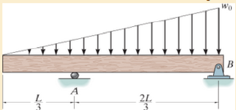
Draw the shear and moment diagrams for the beam.
Prob. 6–27
Expert Solution & Answer

Trending nowThis is a popular solution!

Students have asked these similar questions
A prototype automobile is designed to travel at 65 km/hr. A model of this design is tested in a wind tunnel with identical standard sea-
level air properties at a 1:5 scale. The measured model drag is 529 N, enforcing dynamic similarity. Determine (a) the drag force on the
prototype and (b) the power required to overcome this drag. See the equation
Vm
m
=
D
V Dm
(a) Dp = i
(b) Pp = i
N
hp
A new blimp will move at 6 m/s in 20°C air, and we want to predict the drag force. Using a 1: 14-scale model in water at 20°C and
measuring a 2500-N drag force on the model, determine (a) the required water velocity, (b) the drag on the prototype blimp and, (c) the
power that will be required to propel it through the air.
(a) Vm = i
(b) Dp = i
(c) Pp = i
m/s
N
W
Drag measurements were taken for a sphere, with a diameter of 5 cm, moving at 3.7 m/s in water at 20°C. The resulting drag on the
sphere was 10 N. For a balloon with 1-m diameter rising in air with standard temperature and pressure, determine (a) the velocity if
Reynolds number similarity is enforced and (b) the drag force if the drag coefficient in the equation below is the dependent pi term.
li ε pVI
D
1
= CD = Q
μ
(a) Vp = i
(b) Dp = i
m/s
N
Chapter 6 Solutions
MECHANICS OF MATERIALS-TEXT
Ch. 6.2 - In each case, the beam is subjected to the...Ch. 6.2 - and then draw the shear and moment diagrams for...Ch. 6.2 - In each case, express the shear and moment...Ch. 6.2 - In each case, express the shear and moment...Ch. 6.2 - In each case, express the shear and moment...Ch. 6.2 - In each case, draw the shear and moment diagrams...Ch. 6.2 - In each case, draw the shear and moment diagrams...Ch. 6.2 - In each case, draw the shear and moment diagrams...Ch. 6.2 - In each case, draw the shear and moment diagrams...Ch. 6.2 - If the force applied to the handle of the load...
Ch. 6.2 - Draw the shear and moment diagrams for the shaft....Ch. 6.2 - The crane is used to support the engine, which has...Ch. 6.2 - Prob. 6.4PCh. 6.2 - •6–5. Draw the shear and moment diagrams for the...Ch. 6.2 - Express the internal shear and moment in terms of...Ch. 6.2 - Prob. 6.7PCh. 6.2 - Prob. 6.8PCh. 6.2 - Prob. 6.9PCh. 6.2 - Members ABC and BD of the counter chair are...Ch. 6.2 - Prob. 6.11PCh. 6.2 - A reinforced concrete pier is used to support the...Ch. 6.2 - Prob. 6.13PCh. 6.2 - The industrial robot is held in the stationary...Ch. 6.2 - Determine the placement distance a of the roller...Ch. 6.2 - Express the internal shear and moment in the...Ch. 6.2 - Draw the shear and moment diagrams for the beam,...Ch. 6.2 - Draw the shear and moment diagrams for the beam....Ch. 6.2 - Draw the shear and moment diagrams for the...Ch. 6.2 - The 150-lb man sits in the center of the boat,...Ch. 6.2 - Prob. 6.22PCh. 6.2 - The footing supports the load transmitted by the...Ch. 6.2 - Express the shear and moment in terms of x for 0 ...Ch. 6.2 - Draw the shear and moment diagrams for the beam...Ch. 6.2 - Draw the shear and moment diagrams for the beam....Ch. 6.2 - Draw the shear and moment diagrams for the beam....Ch. 6.2 - Prob. 6.29PCh. 6.2 - 6–30. The beam is bolted or pinned at A and rests...Ch. 6.2 - The support at A allows the beam to slide freely...Ch. 6.2 - The smooth pin is supported by two leaves A and B...Ch. 6.2 - The shaft is supported by a smooth thrust bearing...Ch. 6.2 - Draw the shear and moment diagrams for the...Ch. 6.2 - Draw the shear and moment diagrams for the beam....Ch. 6.2 - Prob. 6.36PCh. 6.2 - Draw the shear and moment diagrams for the beam...Ch. 6.2 - The beam is used to support a uniform load along...Ch. 6.2 - Draw the shear and moment diagrams for the double...Ch. 6.2 - Draw the shear and moment diagrams for the simply...Ch. 6.2 - The compound beam is fixed at A, pin connected at...Ch. 6.2 - Draw the shear and moment diagrams for the...Ch. 6.2 - The compound beam is fixed at A, pin connected at...Ch. 6.2 - Draw the shear and moment diagrams for the beam....Ch. 6.2 - A short link at B is used to connect beams AB and...Ch. 6.2 - 6–46. Determine the placement b of the hooks to...Ch. 6.4 - Determine the moment of inertia of the cross...Ch. 6.4 - Determine the location of the centroid, y, and the...Ch. 6.4 - In each case, show how the bending stress acts on...Ch. 6.4 - Sketch the bending stress distribution over each...Ch. 6.4 - If the beam is subjected to a bending moment of M...Ch. 6.4 - If the beam is subjected to a bending moment of M...Ch. 6.4 - If the beam is subjected to a bending moment of M...Ch. 6.4 - If the beam is subjected to a bending moment of M...Ch. 6.4 - If the beam is subjected to a bending moment of M...Ch. 6.4 - Prob. 6.47PCh. 6.4 - Determine the moment M that will produce a maximum...Ch. 6.4 - Determine the maximum tensile and compressive...Ch. 6.4 - 6–50. A member has the triangular cross section...Ch. 6.4 - Prob. 6.51PCh. 6.4 - Prob. 6.52PCh. 6.4 - Prob. 6.53PCh. 6.4 - If the built-up beam is subjected to an internal...Ch. 6.4 - If the built-up beam is subjected to an internal...Ch. 6.4 - Prob. 6.56PCh. 6.4 - Prob. 6.57PCh. 6.4 - Prob. 6.58PCh. 6.4 - Prob. 6.59PCh. 6.4 - Prob. 6.60PCh. 6.4 - 6–61. The beam is subjected to a moment of 15 kip...Ch. 6.4 - 6–62. A box beam is constructed from four pieces...Ch. 6.4 - Prob. 6.63PCh. 6.4 - The axle of the freight car is subjected to a...Ch. 6.4 - A shaft is made of a polymer having an elliptical...Ch. 6.4 - Solve Prob. 6-65 if the moment M = 50 N m is...Ch. 6.4 - Prob. 6.67PCh. 6.4 - The shaft is supported by smooth journal bearings...Ch. 6.4 - Prob. 6.69PCh. 6.4 - Prob. 6.70PCh. 6.4 - The boat has a weight of 2300 lb and a center of...Ch. 6.4 - Determine the absolute maximum bending stress in...Ch. 6.4 - Determine the smallest allowable diameter of the...Ch. 6.4 - The pin is used to connect the three links...Ch. 6.4 - The shaft is supported by a thrust bearing at A...Ch. 6.4 - Prob. 6.76PCh. 6.4 - If the beam is subjected to an internal moment of...Ch. 6.4 - If the allowable tensile and compressive stress...Ch. 6.4 - If the beam is subjected to an internal moment of...Ch. 6.4 - If the beam is subjected to a moment of M = 100 kN...Ch. 6.4 - If the beam is made of material having an...Ch. 6.4 - The shaft is supported by a smooth thrust bearing...Ch. 6.4 - The shaft is supported by a thrust bearing at A...Ch. 6.4 - If the intensity of the load w = 15 kN/m,...Ch. 6.4 - If the allowable bending stress is allow = 150...Ch. 6.4 - Prob. 6.86PCh. 6.4 - Prob. 6.87PCh. 6.4 - *6–88. If the beam has a square cross section of 9...Ch. 6.4 - If the compound beam in Prob. 642 has a square...Ch. 6.4 - If the beam in Prob. 628 has a rectangular cross...Ch. 6.4 - Determine the absolute maximum bending stress in...Ch. 6.4 - Determine, to the nearest millimeter, the smallest...Ch. 6.4 - 6–93. The wing spar ABD of a light plane is made...Ch. 6.4 - Prob. 6.94PCh. 6.4 - Prob. 6.95PCh. 6.4 - A log that is 2 ft in diameter is to be cut into a...Ch. 6.4 - A log that is 2 ft in diameter is to be cut into a...Ch. 6.4 - If the beam in Prob.63 has a rectangular cross...Ch. 6.4 - Prob. 6.99PCh. 6.4 - If d = 450 mm, determine the absolute maximum...Ch. 6.4 - If the allowable bending stress is allow = 6 MPa,...Ch. 6.4 - Prob. 6.102PCh. 6.4 - 6–103. If the overhanging beam is made of wood...Ch. 6.5 - Determine the bending stress at corners A and B....Ch. 6.5 - Determine the maximum bending stress in the beams...Ch. 6.5 - The member has a square cross section and is...Ch. 6.5 - The member has a square cross section and is...Ch. 6.5 - Consider the general case of a prismatic beam...Ch. 6.5 - 6–107. If the beam is subjected to the internal...Ch. 6.5 - 6-108. If the wood used for the T-beam has an...Ch. 6.5 - 6-109. The box beam is subjected to the internal...Ch. 6.5 - 6-110. If the wood used for the box beam has an...Ch. 6.5 - 6-111. If the beam is subjected to the internal...Ch. 6.5 - 6-112. If the beam is made from a material having...Ch. 6.5 - Prob. 6.113PCh. 6.5 - 6-114. The T-beam is subjected to a bending moment...Ch. 6.5 - 6-115. The beam has a rectangular cross section....Ch. 6.5 - For the section, Iy' = 31.7(10-6) m4, Iz' =...Ch. 6.5 - For the section, Iy' = 31.7(10-6) m4, Iz' =...Ch. 6.5 - If the applied distributed loading of w = 4 kN/m...Ch. 6.5 - Determine the maximum allowable intensity w of the...Ch. 6.9 - The composite beam is made of steel (A) bonded to...Ch. 6.9 - The composite beam is made of steel (A) bonded to...Ch. 6.9 - Segment A of the composite beam is made from...Ch. 6.9 - Segment A of the composite beam is made from...Ch. 6.9 - Prob. 6.124PCh. 6.9 - The wooden section of the beam is reinforced with...Ch. 6.9 - The wooden section of the beam is reinforced with...Ch. 6.9 - Prob. 6.127PCh. 6.9 - The steel channel is used to reinforce the wood...Ch. 6.9 - Prob. 6.129PCh. 6.9 - 6-130. The beam is made from three types of...Ch. 6.9 - 6-131. The concrete beam is reinforced with three...Ch. 6.9 - *6-132. The wide-flange section is reinforced with...Ch. 6.9 - Prob. 6.133PCh. 6.9 - If the beam is subjected to a moment of M = 45 kN...Ch. 6.9 - Prob. 6.135PCh. 6.9 - For the curved beam in Fig. 640a, show that when...Ch. 6.9 - The curved member is subjected to the moment of M...Ch. 6.9 - The curved member is made from material having an...Ch. 6.9 - The curved beam is subjected to a moment of M = 40...Ch. 6.9 - The curved beam is made from material having an...Ch. 6.9 - If P = 3 kN, determine the bending stress at...Ch. 6.9 - If the maximum bending stress at section a-a is...Ch. 6.9 - The elbow of the pipe has an outer radius of 0.75...Ch. 6.9 - Prob. 6.144PCh. 6.9 - Prob. 6.145PCh. 6.9 - Prob. 6.146PCh. 6.9 - Prob. 6.147PCh. 6.9 - Prob. 6.148PCh. 6.9 - Prob. 6.149PCh. 6.9 - 6-150. The bar is subjected to a moment of M = 153...Ch. 6.9 - Prob. 6.151PCh. 6.9 - Prob. 6.152PCh. 6.9 - Prob. 6.153PCh. 6.9 - 6-154. The simply supported notched bar is...Ch. 6.9 - Prob. 6.155PCh. 6.9 - *6-156. Determine the length L of the center...Ch. 6.9 - Prob. 6.157PCh. 6.10 - Determine the shape factor for the wide-flange...Ch. 6.10 - 6-159. The beam is made of an elastic plastic...Ch. 6.10 - Prob. 6.160PCh. 6.10 - Prob. 6.161PCh. 6.10 - Prob. 6.162PCh. 6.10 - Determine the plastic moment Mp that can be...Ch. 6.10 - Determine the shape factor for the beam. Prob....Ch. 6.10 - The beam is made of elastic perfectly plastic...Ch. 6.10 - Determine the shape factor for the beam. Prob....Ch. 6.10 - The beam is made of an elastic perfectly plastic...Ch. 6.10 - Prob. 6.168PCh. 6.10 - Prob. 6.169PCh. 6.10 - 6-170. The box beam is made from an...Ch. 6.10 - 6-171. The beam is made from elastic-perfectly...Ch. 6.10 - *6-172. Determine the shape factor for the...Ch. 6.10 - Prob. 6.173PCh. 6.10 - Prob. 6.174PCh. 6.10 - 6-175. The box beam is made from an...Ch. 6.10 - The wide-flange member is made from an elastic...Ch. 6.10 - Prob. 6.177PCh. 6.10 - The plexiglass bar has a stress-strain curve that...Ch. 6.10 - The stress-strain diagram for a titanium alloy can...Ch. 6.10 - A beam is made from polypropylene plastic and has...Ch. 6.10 - Prob. 6.181PCh. 6.10 - The bar is made of an aluminum alloy having a...Ch. 6 - Using appropriate measurements and data, explain...Ch. 6 - Determine the shape factor for the wide-flange...Ch. 6 - Prob. 6.184RPCh. 6 - The compound beam consists of two segments that...Ch. 6 - The composite beam consists of a wood core and two...Ch. 6 - 6-187. Solve Prob. 6-186 if the moment is applied...Ch. 6 - If it resists a moment of M = 125 N m, determine...Ch. 6 - Determine the maximum bending stress in the handle...Ch. 6 - The curved beam is subjected to a bending moment...Ch. 6 - Determine the shear and moment in the beam as...Ch. 6 - A wooden beam has a square cross section as shown...Ch. 6 - Draw the shear and moment diagrams for the shaft...Ch. 6 - The strut has a square cross section a by a and is...
Knowledge Booster


Learn more about
Need a deep-dive on the concept behind this application? Look no further. Learn more about this topic, mechanical-engineering and related others by exploring similar questions and additional content below.Similar questions
- Calculate the forces in all members of the truss shown using either the method of joints or the method of sectionsarrow_forward20-4-2025 Exam-2-Tribology Q1: What are the assumptions of hydrodynamic lubrication theory: Q2: Explain with sketch the cycle or process of engine lubrication system-pressurized lubrication system Q3: A short bearing is designed to operate with an eccentricity ratio = 0. 7. The journal diameter is 60 mm, and its speed is 1300 r.p.m. The journal is supported by a short hydrodynamic bearing of length L/D = 0. 5, and clearance ratio C/R = 103. The radial load on the bearing is 9800 N. a. Find the Sommerfeld number. b. Find the minimum viscosity of the lubricant for operating at ε = 0.7 c. Select a lubricant if the average bearing operating temperature is 70°c Q4: Two parallel circular disks of 100 mm diameter have a clearance of Imm between them. Under load, the downward velocity of the upper disk is 2 m/s. At the same time, the lower disk is stationary. The clearance is full of SAE 40 oil at a temperature of 60°c. a. Find the load on the upper disk that results in the instantaneous…arrow_forwardTribobolgy 15/2022 Monthly Exam. Automobile Eng. Dert 2nd Semster/3rd class Max. Mark: 100% 7. Viscosity of multi-grade oils (a) Reduces with temperature (c) is less sensitive to temperature (b) Increases with temperature (d) None of the above 8. In a hydrodynamic journal bearing if eccentricity ratio = 1, it means (a) Journal/shaft is subjected to no load and the rotational speed is very high. (b) Journal is subjected to no load and the rotational speed is moderate (c) Journal is subjected to very light load and the rotational speed is very high. (d) Journal is subjected to very high load and the rotational speed is negligible. Q4/ The journal speed of a 100mm diameter journal is 2500 rpm. The journal is supported by a short hydrodynamic bearing of length L=0.6D, eccentricity ratio = 0.75 and a clearance ratio C/R=0.001. The radial load on the bearing is 10 kN. The lubricant is SAE 30, and the operating temperature of the lubricant in the bearing is 700C. 1- Assume…arrow_forward
- 1 of 2 Monthly Exam. Automobile Eng. Dert 2nd Semster/3rd class Max. Mark: 100% Q1/A/ Compare between the long and short journal bearings B/ With the help of Stribeck's curve, discuss different regimes of lubrication. C/ Explain the importance of Tribology in the design of different machine elements Q2 /A/ According to the SAE viscosity grading system all engine oils are divided into two classes: monograde and multi-grade. Compare between them? B/What are the differences between grease and Synthetic oils C/ Explain the effect of eccentricity ratio & with respect to hydrodynamic journal bearing. Q3/A/ What are the major factors which affect the selection of lubricants? B/What are the criteria to classify sliding bearings? C/ Answer of the following: 1. According to the SAE viscosity classification, the oil (SAE 40) is lower viscosity than the oil (SAE 20) at the same temperature. (True or False) 2. For a slow speed-highly loaded bearing, used oils of high viscosity; while for high-speed…arrow_forwardThe uniform rods have a mass per unit length of 10kg/m . (Figure 1)If the dashpot has a damping coefficient of c=50N⋅s/m , and the spring has a stiffness of k=600N/m , show that the system is underdamped, and then find the pendulum's period of oscillation.arrow_forward10-50. The principal plane stresses and associated strains in a plane at a point are σ₁ = 30 ksi, σ₂ = -10 ksi, e₁ = 1.14(10-3), €2=-0.655(103). Determine the modulus of elasticity and Poisson's ratio. emps to plum... Wednesday FI a וח 2 Q Search 48 F5 - F6 4+ F7 FB F9 FIO FII F12 & * S 6 7 8 9 ㅁ F2 # *F3 3 $ 4 F4 % W E R T Y ப S ALT D F G H X C V B N J Σ H L ว { P [ ] ALT " DELETE BACKSPACE NUM LOCK T 7 HOME ENTER 4 PAUSE SHIFT CTRL Earrow_forward
- 10−9. The state of strain at the point has components of ϵx = −100(10−6), ϵy = −200(10−6), and γxy=100(10−6). Use the strain transformation equations to determine (a) the in-plane principal strains and (b) the maximum in-plane shear strain and average normal strain. In each case specify the orientation of the element and show how the strains deform the element within the x−y plane.arrow_forwardThe strain gage is placed on the surface of the steel boiler as shown. If it is 0.5 in. long, determine the pressure in the boiler when the gage elongates 0.2(10−3) in. The boiler has a thickness of 0.5 in. and inner diameter of 60 in. Also, determine the maximum x, y in-plane shear strain in the material. Take Est=29(103)ksi, vst=0.3.arrow_forward(read image, answer given)arrow_forward
- 6/86 The connecting rod AB of a certain internal-combustion engine weighs 1.2 lb with mass center at G and has a radius of gyration about G of 1.12 in. The piston and piston pin A together weigh 1.80 lb. The engine is running at a constant speed of 3000 rev/min, so that the angular velocity of the crank is 3000(2)/60 = 100л rad/sec. Neglect the weights of the components and the force exerted by the gas in the cylinder compared with the dynamic forces generated and calculate the magnitude of the force on the piston pin A for the crank angle 0 = 90°. (Suggestion: Use the alternative moment relation, Eq. 6/3, with B as the moment center.) Answer A = 347 lb 3" 1.3" B 1.7" PROBLEM 6/86arrow_forward6/85 In a study of head injury against the instrument panel of a car during sudden or crash stops where lap belts without shoulder straps or airbags are used, the segmented human model shown in the figure is analyzed. The hip joint O is assumed to remain fixed relative to the car, and the torso above the hip is treated as a rigid body of mass m freely pivoted at O. The center of mass of the torso is at G with the initial position of OG taken as vertical. The radius of gyration of the torso about O is ko. If the car is brought to a sudden stop with a constant deceleration a, determine the speed v relative to the car with which the model's head strikes the instrument panel. Substitute the values m = 50 kg, 7 = 450 mm, r = 800 mm, ko = 550 mm, 0 = 45°, and a = 10g and compute v. Answer v = 11.73 m/s PROBLEM 6/85arrow_forwardUsing AutoCADarrow_forward
arrow_back_ios
SEE MORE QUESTIONS
arrow_forward_ios
Recommended textbooks for you
 Elements Of ElectromagneticsMechanical EngineeringISBN:9780190698614Author:Sadiku, Matthew N. O.Publisher:Oxford University Press
 Mechanics of Materials (10th Edition)Mechanical EngineeringISBN:9780134319650Author:Russell C. HibbelerPublisher:PEARSON
 Thermodynamics: An Engineering ApproachMechanical EngineeringISBN:9781259822674Author:Yunus A. Cengel Dr., Michael A. BolesPublisher:McGraw-Hill Education
 Control Systems EngineeringMechanical EngineeringISBN:9781118170519Author:Norman S. NisePublisher:WILEY
 Mechanics of Materials (MindTap Course List)Mechanical EngineeringISBN:9781337093347Author:Barry J. Goodno, James M. GerePublisher:Cengage Learning
 Engineering Mechanics: StaticsMechanical EngineeringISBN:9781118807330Author:James L. Meriam, L. G. Kraige, J. N. BoltonPublisher:WILEY
Elements Of Electromagnetics
Mechanical Engineering
ISBN:9780190698614
Author:Sadiku, Matthew N. O.
Publisher:Oxford University Press
Mechanics of Materials (10th Edition)
Mechanical Engineering
ISBN:9780134319650
Author:Russell C. Hibbeler
Publisher:PEARSON
Thermodynamics: An Engineering Approach
Mechanical Engineering
ISBN:9781259822674
Author:Yunus A. Cengel Dr., Michael A. Boles
Publisher:McGraw-Hill Education
Control Systems Engineering
Mechanical Engineering
ISBN:9781118170519
Author:Norman S. Nise
Publisher:WILEY
Mechanics of Materials (MindTap Course List)
Mechanical Engineering
ISBN:9781337093347
Author:Barry J. Goodno, James M. Gere
Publisher:Cengage Learning
Engineering Mechanics: Statics
Mechanical Engineering
ISBN:9781118807330
Author:James L. Meriam, L. G. Kraige, J. N. Bolton
Publisher:WILEY
Understanding Shear Force and Bending Moment Diagrams; Author: The Efficient Engineer;https://www.youtube.com/watch?v=C-FEVzI8oe8;License: Standard YouTube License, CC-BY
Bending Stress; Author: moodlemech;https://www.youtube.com/watch?v=9QIqewkE6xM;License: Standard Youtube License