Concept explainers
Videos
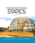
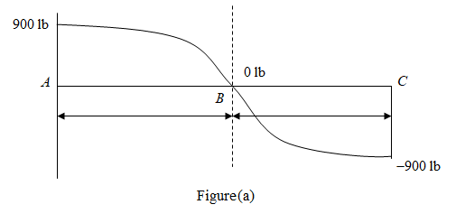
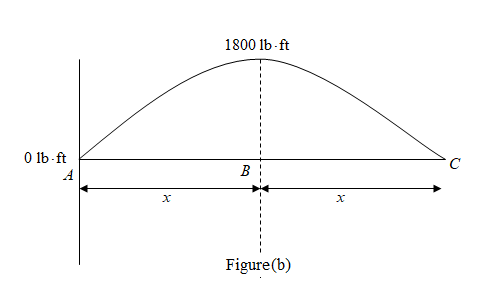
For the beam shown, derive the expressions for V and M, and draw the shear force and bending moment diagrams. Neglect the weight of the beam.
Derive equation for
Answer to Problem 6.31P
The equation for
Explanation of Solution
Draw the Free body diagram for the beam as shown below.
Write the expression for the equilibrium of forces in
Here,
Take the summation of all the forces in
Simplify the above expression.
Here,
Take moment about point
Substitute
Substitute
Simplify the above for
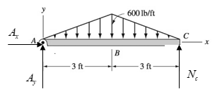
Take section
From the above diagram, by the property of similar triangles magnitude of UVL at distance
Simplify the above expression for
Here,
Take shear force on left side of the section
Here,
Substitute
Take moment about section
Here,
Substitute
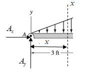
Take section
From the above diagram, by the property of similar triangles magnitude of UVL at distance
Simplify the above expression for
Take shear force on left side of the section
Here,
Substitute
Take moment about section
Substitute
Simplify the above expression.
Thus, from equation (2) and (4) the equation for
Draw the shear force diagram for the beam as shown below.
Draw the Bending moment diagram for the beam as shown below.
Want to see more full solutions like this?
Chapter 6 Solutions
International Edition---engineering Mechanics: Statics 4th Edition


- A vertical .2m by .2m square plate is exposed to saturated water vapor at atmospheric pressure. If the surface temperature is 80 degrees C and the flow is laminar, estimate the loal heat transfer coefficents at the middles and at the bottom of the plate.arrow_forwardA transformer that is 10 cm long, 6.2 cm wide, and 5 cm high is to be cooled by attaching a 10 cm by 6.2 cm wide polished aluminum heat sink(emissivity=.03) to its top surface. The heat sink has seven fins, which are 5 mm high, 2mm thick, and 10 cm long. A fan blows air at 25 degrees C parallel to the passages between the fins. The heat sink is to dissipate 12W of heat, and the base temp of the ehat sink is not to exceed 60 degrees C. Assuming the fins and the base plate to be nearly isothermal and the radiation heat transfer to be negligible, determine the minimum free-stream velocity the fan needs to supply to avoid overheating. Assume the flow is laminar over the entire finned surface of the transformer.arrow_forwardI need a mechanical engineering expert to solve this question,no Ai pleasearrow_forward
- Can you give me the meaning of Combination spanner and Give Examples of Spannersarrow_forwardHW8 A shaft fitted with a flywheel rotates at 650 r.p.m. and drives a machine. The torque of machine varies in a cyclic manner over a period of 2 revolutions. The torque rises from 650 N-m to 2200 N-m uniformly during 110° and remains constant for the following 270°. It then falls uniformly to 600 N-m during the next 100° and remains constant for the end cycle, the cycle being repeated thereafter. Determine the power required to drive the machine and percentage fluctuation in speed, if the driving torque applied to the shaft is constant and the mass of the flywheel is 180 kg with radius of gyration of 35 cm. HW9arrow_forwardunits of h. show all workarrow_forward
- 4. Steam flows steadily through a turbine at a rate of 47,000 lbm/h, entering at 1000 psia and 800°F and leaving at 6 psia as saturated vapor. If the power generated by the turbine is 3.7 MW, determine the rate of heat loss from the steam.arrow_forward3. Water enters the constant 125-mm inside-diameter tubes of a boiler at 7.5 MPa and 60°C and leaves the tubes at 6 MPa and 500°C with a velocity of 75 m/s. Calculate the velocity of the water at the tube inlet and the inlet volume flow rate.arrow_forward2. A piston-cylinder device contains 2.4 kg of nitrogen initially at 120 kPa and 27°C. The nitrogen is now compressed slowly in a polytropic process during which PV1.3 = constant until the volume is reduced by one-half. Determine the work done and the heat transfer for this process.arrow_forward
- 1. 1.25 m³ of saturated liquid water at 225°C is expanded isothermally in a closed system until its quality is 75 percent. Determine the total work produced by this expansion, in kJ.arrow_forwardAn undamped single-degree-of-freedom system is subjected to dynamic excitation as shown in Figure 1.• System properties: m = 1, c = 0, k = (6π)2.• Force excitation: p(t) = posin(ωt) where po = 9 and ω = 2π.• Initial conditions: u(t = 0) = 0 and ̇u(t = 0) = 0.Please, complete Parts (a) through (d) using any computational tool of your preference. The preferred toolis MATLAB. Print and turn in a single pdf file that will include your code/calculations and your plots.(a) Generate the solution using a linear interpolation of the load over each time step (note that hereyou can use the undamped coefficients). Plot the displacement response for the first 4 seconds andcompare to the exact closed form solution. Repeat using the following time step sizes, ∆t = 0.01,0.05, 0.15, 0.20 seconds. Include the closed form solution and the solutions for different ∆t values in asingle plot. Please, provide your observations by comparing the closed form solution with the solutionsderived using the four…arrow_forwardAssume multiple single degree of freedom systems with natural periods T ∈ [0.05, 2.00] seconds with in-crement of period dT = 0.05 seconds. Assume three cases of damping ratio: Case (A) ξ = 0%; Case (B)ξ = 2%; Case (C) ξ = 5%. The systems are initially at rest. Thus, the initial conditions are u(t = 0) = 0 anḋu(t = 0) = 0. The systems are subjected to the base acceleration that was provided in the ElCentro.txt file(i.e., first column). For the systems in Case (A), Case (B), and Case (C) and for each natural period computethe peak acceleration, peak velocity, and peak displacement responses to the given base excitation. Please,use the Newmark method for β = 1/4 (average acceleration) to compute the responses. Create threeplots with three lines in each plot. The first plot will have the peak accelerations in y-axis and the naturalperiod of the system in x-axis. The second plot will have the peak velocities in y-axis and the natural periodof the system in x-axis. The third plot will have…arrow_forward
 International Edition---engineering Mechanics: St...Mechanical EngineeringISBN:9781305501607Author:Andrew Pytel And Jaan KiusalaasPublisher:CENGAGE L