
Concept explainers
Videos
Using appropriate measurements and data, explain how to determine the bending stress in the blade.
C6–1
Answer to Problem 6.1CP
The bending stress in the blade is
Explanation of Solution
Given information:
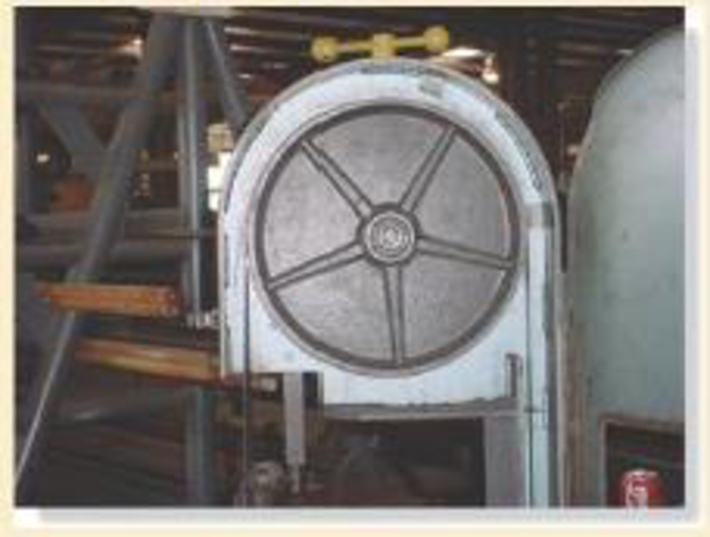
- The steel saw blade passes over the drive wheel of the band saw.
- Use appropriate measurements and data.
Explanation:
The contact area of the cable is upper half portion of the drive wheel. The, the upper half portion of the wheel will undergo stress.
Show the free-body diagram of the drive wheel as in Figure 1.
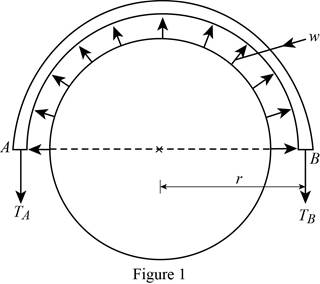
The force induced in the drive wheel will be uniformly distributed.
The circumferential distance of the circular section is
Convert the semi-circular section into beam section as in Figure 2.
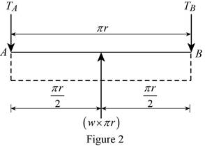
Determine the tension in the cable:
Moment about point A:
Determine the tension in the cable at point B by taking moment about point A.
Along the vertical direction:
Determine the tension in the cable at point A by resolving the vertical component of forces.
Show the calculation of values as follows:
Solve Equation (1).
Substitute
Maximum Bending moment:
The maximum bending moment will occur where the shear force changes sign
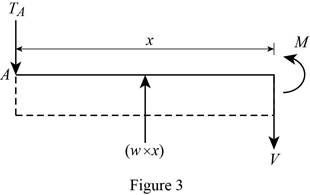
Consider a section at a distance x from left end of the beam.
Show the free body diagram of the section as in Figure 3.
Along the vertical direction:
Determine the shear force at the section by resolving the vertical component of forces.
Moment about the section:
Determine the moment at the section by taking moment about the section.
Substitute 0 for V and
Thus, the maximum bending moment will occur at a distance
Substitute
Bending stress:
Calculate the bending stress in the blade using the flexure formula.
Here, c is the distance between the centroid and the extreme fibre and I is moment of inertia of the band saw.
Consider the band saw is in rectangular cross section.
The value of c is
The moment of inertia of the band saw is
Here, b is width of the section and d is depth of the section.
Substitute
Thus, the bending stress in the blade is
Want to see more full solutions like this?
Chapter 6 Solutions
Mechanics of Materials Plus Mastering Engineering with Pearson eText - Access Card Package (10th Edition)


- 1. The rotating steel shaft is simply supported by bearings at points of B and C, and is driven by a spur gear at D, which has a 6-in pitch diameter. The force F from the drive gear acts at a pressure angle of 20°. The shaft transmits a torque to point A of TA =3000 lbĘ in. The shaft is machined from steel with Sy=60kpsi and Sut=80 kpsi. (1) Draw a shear force diagram and a bending moment diagram by F. According to your analysis, where is the point of interest to evaluate the safety factor among A, B, C, and D? Describe the reason. (Hint: To find F, the torque Tд is generated by the tangential force of F (i.e. Ftangential-Fcos20°) When n=2.5, K=1.8, and K₁ =1.3, determine the diameter of the shaft based on (2) static analysis using DE theory (note that fatigue stress concentration factors need to be used for this question because the loading condition is fatigue) and (3) a fatigue analysis using modified Goodman. Note) A standard diameter is not required for the questions. 10 in Darrow_forward3 N2=28 P(diametral pitch)=8 for all gears Coupled to 25 hp motor N3=34 Full depth spur gears with pressure angle=20° N₂=2000 rpm (1) Compute the circular pitch, the center-to-center distance, and base circle radii. (2) Draw the free body diagram of gear 3 and show all the forces and the torque. (3) In mounting gears, the center-to-center distance was reduced by 0.1 inch. Calculate the new values of center-to-center distance, pressure angle, base circle radii, and pitch circle diameters. (4)What is the new tangential and radial forces for gear 3? (5) Under the new center to center distance, is the contact ratio (mc) increasing or decreasing?arrow_forward2. A flat belt drive consists of two 4-ft diameter cast-iron pulleys spaced 16 ft apart. A power of 60 hp is transmitted by a pulley whose speed is 380 rev/min. Use a service factor (Ks) pf 1.1 and a design factor 1.0. The width of the polyamide A-3 belt is 6 in. Use CD=1. Answer the following questions. (1) What is the total length of the belt according to the given geometry? (2) Find the centrifugal force (Fc) applied to the belt. (3) What is the transmitted torque through the pulley system given 60hp? (4) Using the allowable tension, find the force (F₁) on the tight side. What is the tension at the loose side (F2) and the initial tension (F.)? (5) Using the forces, estimate the developed friction coefficient (f) (6) Based on the forces and the given rotational speed, rate the pulley set. In other words, what is the horse power that can be transmitted by the pulley system? (7) To reduce the applied tension on the tight side, the friction coefficient is increased to 0.75. Find out the…arrow_forward
- The tooth numbers for the gear train illustrated are N₂ = 24, N3 = 18, №4 = 30, №6 = 36, and N₁ = 54. Gear 7 is fixed. If shaft b is turned through 5 revolutions, how many turns will shaft a make? a 5 [6] barrow_forwardCE-112 please solve this problem step by step and give me the correct answerarrow_forwardCE-112 please solve this problem step by step and give me the correct answerarrow_forward
- CE-112 solve this problem step by step and give me the correct answer pleasearrow_forwardPlease do not use any AI tools to solve this question. I need a fully manual, step-by-step solution with clear explanations, as if it were done by a human tutor. No AI-generated responses, please.arrow_forwardPlease do not use any AI tools to solve this question. I need a fully manual, step-by-step solution with clear explanations, as if it were done by a human tutor. No AI-generated responses, please.arrow_forward
 International Edition---engineering Mechanics: St...Mechanical EngineeringISBN:9781305501607Author:Andrew Pytel And Jaan KiusalaasPublisher:CENGAGE L
 Mechanics of Materials (MindTap Course List)Mechanical EngineeringISBN:9781337093347Author:Barry J. Goodno, James M. GerePublisher:Cengage Learning