
Videos
a.
Write the expressions of current
a.
Answer to Problem 2P
The current
Explanation of Solution
Given data:
Refer to the given figure in the respective question for the triangular current pulse.
Calculation:
PSPICE:
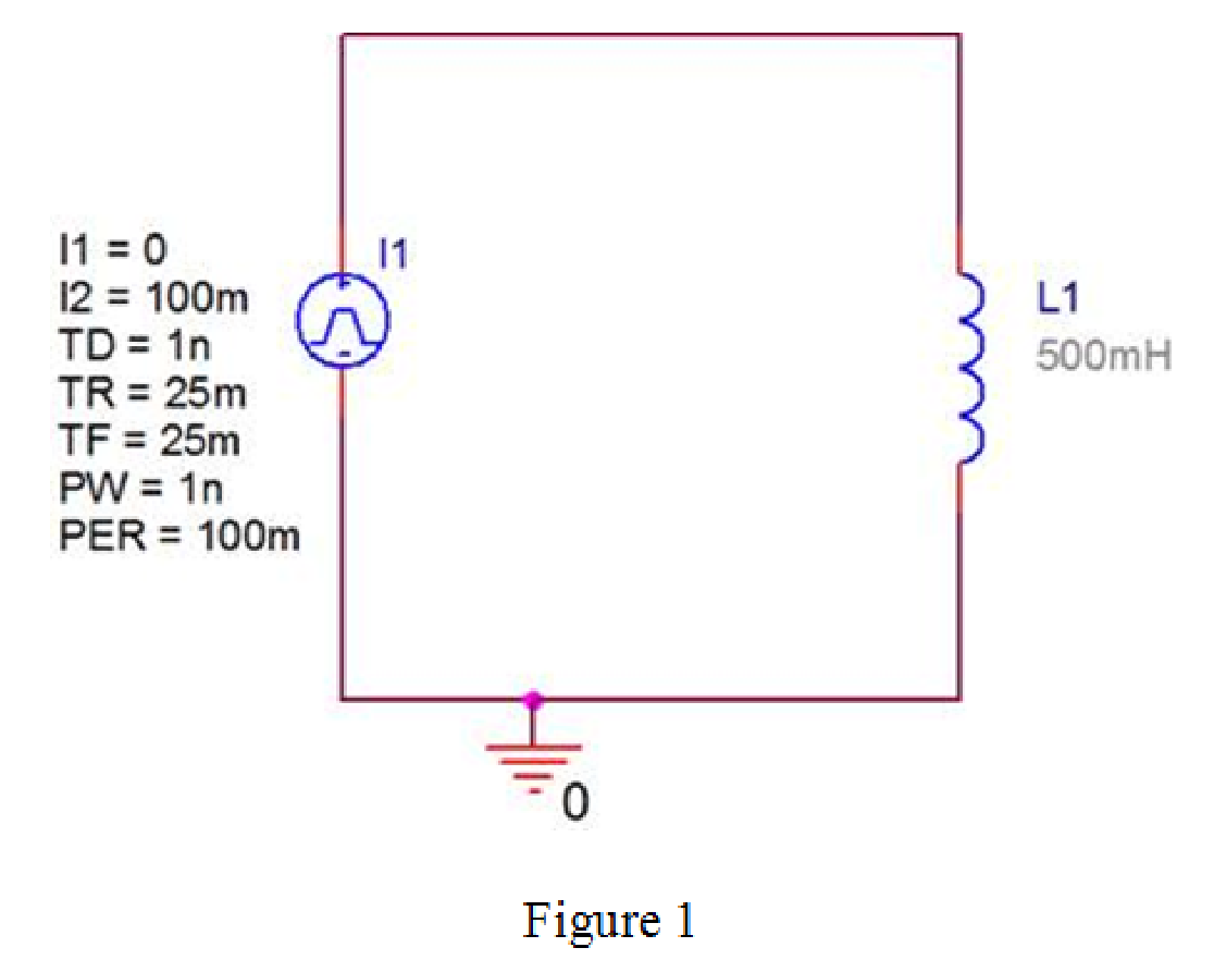
Design the circuit in PSPICE that contains the inductor and the given triangular pulse as shown in Figure 1.
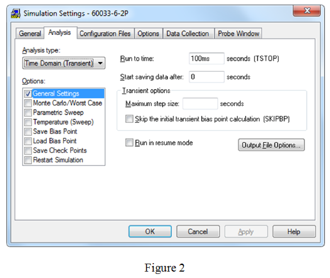
Provide the simulation settings as shown in Figure 2.
Run the circuit and obtain the graph of current versus time as shown n Figure 3.
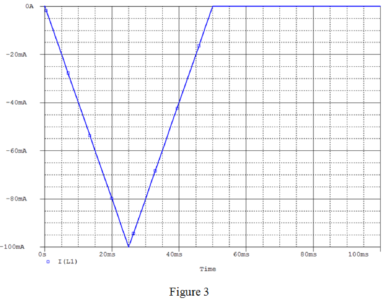
For
From Figure 3, it is concluded that, for
Conclusion:
Thus, the current
b.
Derive the expressions for the inductor voltage, power, and energy.
b.
Answer to Problem 2P
The expressions for the inductor voltage, power, and energy are
Explanation of Solution
Calculation:
Write the expression for the inductor voltage.
Substitute 50 mH for L and
Substitute 50 mH for L and
For
The inductor voltage expression is,
Consider the expression for the power in the inductor.
Substitute
Substitute
For
The power in the inductor is,
For
Calculate the energy in the inductor.
Simplify the equation as follows.
Conclusion:
Thus, the expressions for the inductor voltage, power, and energy are
Want to see more full solutions like this?
Chapter 6 Solutions
Electric Circuits (10th Edition)


- Please solve it by explaining the steps. I am trying to prepare for my exam tomorrow, so any tips and tricks to solve similar problems are highly appreciated. Plus, this is a past exam I am using to prepare.arrow_forwardPlease solve it by explaining the steps. I am trying to prepare for my exam tomorrow, so any tips and tricks to solve similar problems are highly appreciated. Plus, this is a past exam I am using to prepare.arrow_forwardIf C is the circle |z|=4 evaluate ff(z)dz for each of the following functions using residue. Z (a)f(z) = z²-1 Z+1 1 (b)f(z) = = (c)f(z) = z²(z+2) z(z-2)³ z² 1 1 (d) f(z) = = (e) f(z) = (f) f(z) = (z²+3z+2)² z²+z+1 z(z²+6z+4)arrow_forward
- 5. Answer the following questions. Take help from ChatGPT to answer these questions (if you need). Write the answers briefly using your own words with no more than two sentences, and check whether ChatGPT is giving you the appropriate answers in the context of our class. a) What is the Bode plot? What kind of input do we consider for the frequency-response- based method? b) What is the advantage of design using the frequency-response method? c) Define gain margin, phase margin, gain crossover frequency, and phase crossover frequency.arrow_forwardPhase (deg) 3. The Bode diagram of a system is shown below. Magnitude (dB) System: sys -10 Frequency (rad/s): 0.141 Magnitude (dB): -15.6 -20 -30 40 -50 -60 0 -45 -90 -135 101 10° Bode Diagram System: sys Frequency (radis): 10 Magnitude (dB): -18.9 System: sys Frequency (rad/s): 10 Phase (deg):-52.2 101 Frequency (rad/s) 102 103 Find the steady-state output of the system for each of the following inputs. a) u(t) = 100 b) u(t) 100 cos(10 t + 10°) = c) u(t) = 500 + 200 cos(10 t + 10°)arrow_forwardPhase (deg) 270 4. Consider a closed-loop system with unity (negative) feedback. The Bode diagram of the open-loop transfer function is given below. Magnitude (dB) -500 -150 -50 10 dB System Frequency (eds): 6.63 Magnitude (B) 0.0778 Буку Frequency(): 10.1 Magnitude ()-705 Frequency(6.63 Phase (deg): -144 Frequency (rad): 10.1 Phase (deg): -180 101 Frequency (rad) a) Find the gain margin, phase margin, gain crossover frequency, and phase crossover frequency. b) Is the closed-loop system stable? What is the steady-state error for step-input?arrow_forward
- Application of Complex Inversion Integral for Inverse Z-transform Find Z-1 (z-1)(z-2) }arrow_forwardz+4 What is the value of cz²+2z+5 a) If C is the circle |z|=1. dz b) If C is the circle |z+1-i|=2. c) If C is the circle |z+1+i|=2.arrow_forwardz+4 What is the value of √cz²+2z+5 dz Sc a) If C is the circle |z|=1. c) If C is the circle |z+1+i|=2. b) If C is the circle |z+1-i|=2.arrow_forward
 Introductory Circuit Analysis (13th Edition)Electrical EngineeringISBN:9780133923605Author:Robert L. BoylestadPublisher:PEARSON
 Delmar's Standard Textbook Of ElectricityElectrical EngineeringISBN:9781337900348Author:Stephen L. HermanPublisher:Cengage Learning
 Programmable Logic ControllersElectrical EngineeringISBN:9780073373843Author:Frank D. PetruzellaPublisher:McGraw-Hill Education
 Fundamentals of Electric CircuitsElectrical EngineeringISBN:9780078028229Author:Charles K Alexander, Matthew SadikuPublisher:McGraw-Hill Education
 Electric Circuits. (11th Edition)Electrical EngineeringISBN:9780134746968Author:James W. Nilsson, Susan RiedelPublisher:PEARSON
 Engineering ElectromagneticsElectrical EngineeringISBN:9780078028151Author:Hayt, William H. (william Hart), Jr, BUCK, John A.Publisher:Mcgraw-hill Education,