
To derive:
The Equation 6.4a and 6.4b using
Answer to Problem 1QAP
The Equation 6.4a and 6.4b using mechanics of materials principles is shown in conclusion.
Explanation of Solution
Write the expression for engineering stress.
Here, the tensile force is P and cross-sectional area is A.
Write the expression for shear stress.
Here, the normal force is P and shear forces is V.
Conclusion:
Show the diagram of a block element of material of cross-sectional area A that is subjected to a tensile force P, the orientations of the applied stress, the normal stress to this plane, as well as the shear stress taken parallel to this inclined plane.
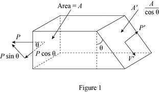
For static equilibrium in the x-direction.
Which means that
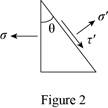
Write the expression for the stress
Write the expression for
Thus, the
Want to see more full solutions like this?
Chapter 6 Solutions
Materials Science and Engineering: An Introduction, 10e WileyPLUS + Abridged Loose-leaf

- 2. For each of the following transfer functions, G(s) = Y(s)/U(s), find the differential equation relating the input u(t) to the output y(t). (s+2)(s+3) (a) G(s) = (s+1)(s+4) (s²+0.4s+1.04) (s+3) (b) G(s)= (s2+0.2s+1)(s+2)(s+4)arrow_forwardDon't use ai to answer I will report you answerarrow_forwardYou will write a program that allows the user to keep track of college locations and details about each location. To begin you will create a College python class that keeps track of the csollege's unique id number, name, address, phone number, maximum students, and average tuition cost. Once you have built the College class, you will write a program that stores College objects in a dictionary while using the College's unique id number as the key. The program should display a menu in this order that lets the user: 1) Add a new College 2) Look up a College 4) Delete an existing College 5) Change an existing College's name, address, phone number, maximum guests, and average tuition cost. 6) Exit the programarrow_forward
- You will write a program that allows the user to keep track of college locations and details about each location. To begin you will create a College python class that keeps track of the csollege's unique id number, name, address, phone number, maximum students, and average tuition cost. Once you have built the College class, you will write a program that stores College objects in a dictionary while using the College's unique id number as the key. The program should display a menu in this order that lets the user: 1) Add a new College 2) Look up a College 4) Delete an existing College 5) Change an existing College's name, address, phone number, maximum guests, and average tuition cost. 6) Exit the programarrow_forwardplease first help me solve this problem find the line of action and them help to find the forces like for example {fx= fy= mz= and determine the shear force in the nailsarrow_forward5. A schematic diagram of a motor connected to a load by gears is shown. Both the motor and the load are modeled as rotating masses with viscous damping. Find the transfer functions Øm/Tm and ØL/Tm. bm Jm Tm 0m N₂ N₁ OL но JL b₁arrow_forward
- 3. Find the transfer function X2/F of the mechanical system in Figure. Κι www b₁ M₁ K2 www M2 b2 X2 F b3arrow_forwardS1(t) Es/Ts 0 S3(t) 0 Es/Ts Ts t S2(t) Es/Ts 0 Es/Ts Ts |7|2 S4(t) Es/Ts t Ts t 0 Ts Ts Ts Es/TS 2 1/ Q1(t) 42(t) Ts 1JT 0 t 0 Ts Ts 2 32 FIGURE 7.3 Set of signals and orthonormal functions for Example 7.1. 53(t)=√√Esq₁(t) S4(t)=-√E542(t) t Tsarrow_forward1. For each of the following differential equations, determine the transfer function Y/U. Determine if the transfer function is proper or strictly proper. is not strictly proper, determine the strictly proper part. If it (a) y(3) = -3y(2) - 3y(1) — 2y + u(2) — - (b) y(3)=-3.5y(2) — 3.5y(1) — y +u(3) — 3.5u(2) + 3.5u(¹) + 3uarrow_forward
- .4. Find the transfer function Ø2/T of the mechanical system in Figure. TG K 02 b₁ b₂ b3arrow_forwardMatlab problem: 1) A BFSK signal is transmitted through a channel with AWGN. Generate similar BFSK received signal plots as shown below. (20 pts) BFSK for eb=1 and npower=0.01 with 500 samples BFSK for eb=1 and npower=0.1 with 500 samples 2.5 2.5 2 1.5 1 0.5 0 -0.5 -1 2 1.5 1 0.5 0.5 -1 -1.5 1.5 -1.5 -1 -0.5 0 0.5 1.5 2 2.5 -1.5 -0.5 0 0.5 1 1.5 2 2.5arrow_forwardAn open channel of square cross section had a flowrate of 17.2 ft³/s when first used. After extended use, the channel became 0.6-filled with silt. Determine the flowrate for this silted condition. Assume the Manning coefficient is the same for all the surfaces. Qs= ! ft³/sarrow_forward
 MATLAB: An Introduction with ApplicationsEngineeringISBN:9781119256830Author:Amos GilatPublisher:John Wiley & Sons Inc
 Essentials Of Materials Science And EngineeringEngineeringISBN:9781337385497Author:WRIGHT, Wendelin J.Publisher:Cengage,
 Industrial Motor ControlEngineeringISBN:9781133691808Author:Stephen HermanPublisher:Cengage Learning
 Basics Of Engineering EconomyEngineeringISBN:9780073376356Author:Leland Blank, Anthony TarquinPublisher:MCGRAW-HILL HIGHER EDUCATION
 Structural Steel Design (6th Edition)EngineeringISBN:9780134589657Author:Jack C. McCormac, Stephen F. CsernakPublisher:PEARSON
 Fundamentals of Materials Science and Engineering...EngineeringISBN:9781119175483Author:William D. Callister Jr., David G. RethwischPublisher:WILEY