
Concept explainers
Videos
(a) To evaluate:
The expression
Answer to Problem 1P
Solution:
The value of the expression
Explanation of Solution
The given expression is,
Assign
Simplify the above equation,
Write the MATLAB script to evaluate the expression
MATLAB Code:
%Evaluate the expression
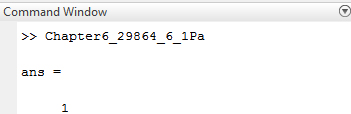
12-4<5.*3
%Assign 1 if the comparison is correct otherwise assign 0.
Save the MATLAB script with name, Chapter6_29864_6_1Pa.m in the current folder. Execute the script by typing the script name at the command window to evaluate the expression
Result:
(b) To evaluate:
The expression
Answer to Problem 1P
Solution:
The value of the expression
Explanation of Solution
The given expression is,
Assign
Simplify the above equation,
Write the MATLAB script to evaluate the expression
MATLAB Code:
%Evaluate the expression
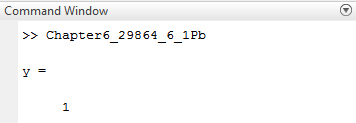
y = 8/4>6*3-4^2>-3
%Assign 1 if the comparison is correct otherwise assign 0.
Save the MATLAB script with name, Chapter6_29864_6_1Pb.m in the current folder. Execute the script by typing the script name at the command window to evaluate the expression
Result:
(c) To evaluate:
The expression
Answer to Problem 1P
Solution:
The value of the expression
Explanation of Solution
The given expression is,
Assign
Simplify the above equation,
Write the MATLAB script to evaluate the expression
MATLAB Code:
%Evaluate the expression
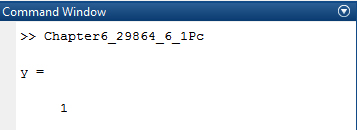
y=-3<(8-12)+2*(5>18/6-4)^2
%Assign 1 if the comparison is correct otherwise assign 0.
Save the MATLAB script with name, Chapter6_29864_6_1Pc.m in the current folder. Execute the script by typing the script name at the command window to evaluate the expression
Result:
(d) To evaluate:
The expression
Answer to Problem 1P
Solution:
The value of the expression
Explanation of Solution
The given expression is,
The sign
Assign
Simplify the above equation,
Write the MATLAB script to evaluate the expression
MATLAB Code:
%Evaluate the expression
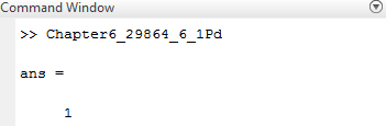
(~5+~0)*6==3+3*~0
%Assign 1 if the comparison is correct otherwise assign 0.
Save the MATLAB script with name, Chapter6_29864_6_1Pd.m in the current folder. Execute the script by typing the script name at the command window to evaluate the expression
Result:
Want to see more full solutions like this?
Chapter 6 Solutions
MATLAB: An Introduction with Applications


- Circuits help please solve and explain. Question in images providedarrow_forward+ V 6.2 A 1.2 A S R 4 Ω Find the source voltage Vs 0.8 Aarrow_forwardDetermine i(t) for t≥ 0 given that the circuit below had been in steady state for a long time prior to t = 0. Also, I₁ = 1 5 A, R₁ =22, R2 =10 Q2, R3 = 32, R4 =7 2, and L=0.15 H. Also fill the table. m L ww R2 t = 0 R₁ 29 R3 R4 Time 0 iL(t) 0 8arrow_forward
- Find the Thévenin equivalent circuit for the portions of the networks in Figure external to the elements between points a and b. a R₁ 2002 I = 0.1 A 0° Xc : 32 Ω R2 = 6802 20 Ω фъarrow_forwardFind the Norton equivalent circuit for the network external to the elements between a and b for the networks in Figure. E1 = 120 V Z 0° R ww 10 Ω Xc XL · 000 802 802 ① I = 0.5 AZ 60° ZL barrow_forwardUsing superposition, determine the current through inductance XL for each network in Figure I = 0.3 A 60° XL 000 802 XC 502 Ω E 10 V0° =arrow_forward
- Find the Thévenin equivalent circuit for the portions of the networks in Figure external to the elements between points a and b. E = 20 VZ0° + R ww 2 ΚΩ Хо XL 000 6ΚΩ 3 ΚΩ b RLarrow_forwardWhat percentage of the full-load current of a thermally protected continuous-duty motor of more than one Hp can the trip current be, if the full-load current is 15 amperes? Ο 122 Ο 140 156 O 170arrow_forwardQ3arrow_forward
 Introductory Circuit Analysis (13th Edition)Electrical EngineeringISBN:9780133923605Author:Robert L. BoylestadPublisher:PEARSON
 Delmar's Standard Textbook Of ElectricityElectrical EngineeringISBN:9781337900348Author:Stephen L. HermanPublisher:Cengage Learning
 Programmable Logic ControllersElectrical EngineeringISBN:9780073373843Author:Frank D. PetruzellaPublisher:McGraw-Hill Education
 Fundamentals of Electric CircuitsElectrical EngineeringISBN:9780078028229Author:Charles K Alexander, Matthew SadikuPublisher:McGraw-Hill Education
 Electric Circuits. (11th Edition)Electrical EngineeringISBN:9780134746968Author:James W. Nilsson, Susan RiedelPublisher:PEARSON
 Engineering ElectromagneticsElectrical EngineeringISBN:9780078028151Author:Hayt, William H. (william Hart), Jr, BUCK, John A.Publisher:Mcgraw-hill Education,