
Videos
The switch in the bottom loop of Fig. P6.1 is closed at t = 0 and then opened at a later time t1. What is the direction of the current I in the top loop (clockwise or counterclockwise) at each of these two times?
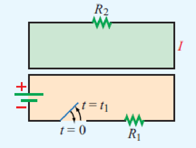
Figure P6.1 Loops of Problem 6.1.
The direction of the current
Answer to Problem 1P
The current in the top loop will be in counter-clockwise direction.
Explanation of Solution
Given data:
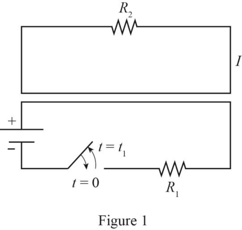
The required diagram is drawn as shown in Figure 1.
Calculation:
The required diagram is drawn as shown in Figure 2 at
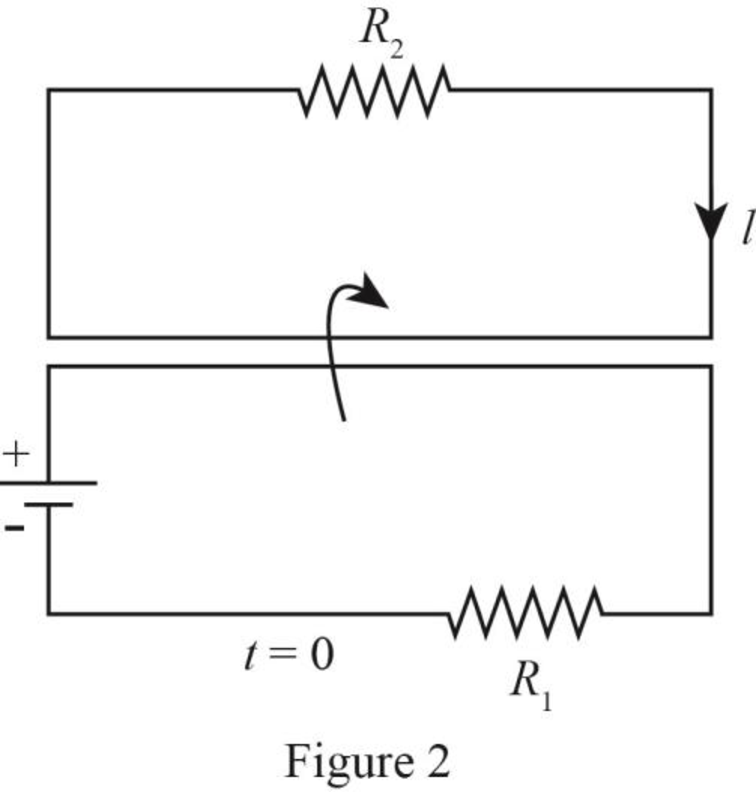
It is observed that at
Hence, the current in the top loop is also momentarily clockwise direction.
From Figure 1, it is observed that there is no current flow in the bottom loop because switch is open. Due to this, there is a decrement of the flux in the secondary loop and if flux decreases then the direction of current will be reversed.
Hence, the current in the top loop will be in counter-clockwise direction.
Conclusion:
Therefore, the current in the top loop will be in counter-clockwise direction.
Want to see more full solutions like this?
Chapter 6 Solutions
Fundamentals of Applied Electromagnetics (7th Edition)
Additional Engineering Textbook Solutions
Java: An Introduction to Problem Solving and Programming (8th Edition)
Concepts Of Programming Languages
Electric Circuits. (11th Edition)
Database Concepts (8th Edition)
Introduction To Programming Using Visual Basic (11th Edition)
Starting Out with Python (4th Edition)


- Choose the best answer 1. The minimum value of the directivity of an antenna is.......... a) Unity b) Zero 2. Very low signal strength in antenna. a) Minor lobes b) Null c) Infinite d) None c) Antenna patterns d) Major lobes 3. the maximum directivity of an antenna that normalized far field pattern is given by? 0≤0≤ and 0 ≤≤π/2,3л/2≤ p ≤ 2π E(0, 4) = {(sin 0 ((sin cos² ) 1/2 0 is a) 7.07dB b) 7.7dB elsewhere c) 8.7dB d) 9dB 4. the depth of penetration of 1 MHz wave in sea water which has conductivity mhos/meter and permeability approximately equal to that of free space is a) 25mm b) 25cm c)25m 5. The free space media can be considered as _ a) Lossy media b) lossless media c) good conductor 6. The input impedance is equal to the load impedance when a) l = 2 b)1=22 c)=4 d) 25km d) a and c .... d) a and barrow_forwardQ.1. choose the appropriate answer 1- When neither E nor H field is transverse to the direction of wave propagation. They are sometimes referred to as ...... a) hybrid mode b) TM mode c) TME modes d) TEM mode 2- If PLF-0 dB means......... a) Power is lost 100% b) Power is lost 0% c) Power is lost 50% d) none of the above 3. The half wave dipole is widely used in more applications compared to other linear antenna lengths, that is because..... a) It has high gain b) its easy matching to coaxial 75 Ohm cable c) low loss d) it has small size 4- The mode distribution for the end view waveguide shown below is a) TM12 b) TM21 c) TE20 end view d) TE02 5. When circular right hand polarized wave incident upon a horizontally polarized wave the PLF is a) 0 b)1 c)0.5 d)0.707arrow_forwarda- Single phase transmission line as in the figure below with the radius of the conductor is 0.5 cm, find the inductance of the total system. 4m 4m ao A B ob od 3m 6marrow_forward
- Please don't use ai to answer I will report you answerarrow_forwardA 3-phase, 4-wire distributor supplies a balanced voltage of 400/230 V to a load consisting of 8 A at p.f. 0-7 lagging for R-phase, 10 A at p.f. 0-8 leading for Y phase and 12 A at unity p.f. for B phase. The resistance of each line conductor is 0.4 2. The reactance of neutral is 0.2 2. Calculate the neutral current, the supply voltage for R phase and draw the phasor diagram. The phase sequence is RYB. IN ER VR Refarrow_forwardA 3-phase, 4-wire distributor supplies a balanced voltage of 400/230 V to a load consisting of 50 A at p.f. 0-866 lagging for R-phase, 30 A at p.f. 0-866 leading for Y phase and 30 A at unity pf. for B phase. The resistance of each line conductor is 0-2 Q. The area of X-section of neutral is half of any line conductor: Calculate the supply end voltage for R phase. The phase sequence is RYB.arrow_forward
- - A 3-phase, 4-wire distributor supplies a balanced voltage of 400/230 V to a load consisting of 8 A at p.f. 0.7 lagging for R-phase, 10 A at p.f. 0-8 leading for Y phase and 12 A at unity p.f. for B phase. The resistance of each line conductor is 0.4 2. The reactance of neutral is 0.2 2. Calculate the neutral current, the supply voltage for R phase and draw the phasor diagram. The phase sequence is RYB.arrow_forwardNo AI WILL REJECTarrow_forwardhelp on this one?arrow_forward
 Introductory Circuit Analysis (13th Edition)Electrical EngineeringISBN:9780133923605Author:Robert L. BoylestadPublisher:PEARSON
 Delmar's Standard Textbook Of ElectricityElectrical EngineeringISBN:9781337900348Author:Stephen L. HermanPublisher:Cengage Learning
 Programmable Logic ControllersElectrical EngineeringISBN:9780073373843Author:Frank D. PetruzellaPublisher:McGraw-Hill Education
 Fundamentals of Electric CircuitsElectrical EngineeringISBN:9780078028229Author:Charles K Alexander, Matthew SadikuPublisher:McGraw-Hill Education
 Electric Circuits. (11th Edition)Electrical EngineeringISBN:9780134746968Author:James W. Nilsson, Susan RiedelPublisher:PEARSON
 Engineering ElectromagneticsElectrical EngineeringISBN:9780078028151Author:Hayt, William H. (william Hart), Jr, BUCK, John A.Publisher:Mcgraw-hill Education,