
Basic Engineering Circuit Analysis
11th Edition
ISBN: 9781118539293
Author: J. David Irwin, R. Mark Nelms
Publisher: WILEY
expand_more
expand_more
format_list_bulleted
Concept explainers
Videos
Textbook Question
thumb_up100%
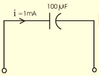
Chapter 6, Problem 1P
An uncharged
Expert Solution & Answer
To determine
The voltage across the capacitor after 4 seconds.
Answer to Problem 1P
Explanation of Solution
Given:
Calculation:
The figure can be drawn as:
The voltage across the capacitor after 4 seconds will be:
Want to see more full solutions like this?
Subscribe now to access step-by-step solutions to millions of textbook problems written by subject matter experts!
Students have asked these similar questions
Can you show how this answer was found?
Can you show how this answer was found?
Can you show how this answer was found:
Chapter 6 Solutions
Basic Engineering Circuit Analysis
Additional Engineering Textbook Solutions
Find more solutions based on key concepts
What is a variables scope?
Starting Out with Python (4th Edition)
The cable attach to the tractor at B exerts a force of 350 lb on the framework Express the force as a Cartesian...
INTERNATIONAL EDITION---Engineering Mechanics: Statics, 14th edition (SI unit)
Complete a recursive definition of the following method: / Precondition: n = 0. Returns 10 to the power n. / pu...
Java: An Introduction to Problem Solving and Programming (8th Edition)
Big data Big data describes datasets with huge volumes that are beyond the ability of typical database manageme...
Management Information Systems: Managing The Digital Firm (16th Edition)
Use the following tables for your answers to questions 3.7 through 3.51 : PET_OWNER (OwnerID, OwnerLasst Name, ...
Database Concepts (8th Edition)
The ________ object is assumed to exist and it is not necessary to include it as an object when referring to it...
Web Development and Design Foundations with HTML5 (8th Edition)
Knowledge Booster


Learn more about
Need a deep-dive on the concept behind this application? Look no further. Learn more about this topic, electrical-engineering and related others by exploring similar questions and additional content below.Similar questions
- Q1 [2 point] Perform 13+10 in the following Adder- Subtractor: A= |B= A3 B3 IB2 B1 A0 BO FAH FAH FAH FA M CO Q2 [2 point] Perform 13-10 in the following Adder- Subtractor: A= B= A3 B3 A2 B2 A1 B1 A0 BO A = = BC= AB FA FA FA FA M COarrow_forwardMatlab Homework (20ps) A BFSK signal is transmitted through a channel with AWGN. Generate similar BFSK received signal plots as shown on next page. (20 pts) BFSK for eb-1 and npower=0.01 with 500 samples BFSK for eb=1 and npower=0.1 with 500 samples 2.5 2.5 2 1.5 1 0.5 0 -0.5 -1 2 1.5 1 0.5 0 0.5 -1 -1.5 1.5 -1.5 -1 -0.5 0 0.5 1 1.5 2 2.5 -1.5 -1 -0.5 0 0.5 1 1.5 2 2.5arrow_forwardCan you show how this answer was found?arrow_forward
- 1. You are to design a 9-volt battery operated baseband PAM communication system that must last great than 10 years without replacing the batteries. The application requires a BER of <10^-4 and a data rate of 200bps. The channel can be modeled as AWGN with a noise power spectral density of 10^-9 W/Hz and a channel loss of 10 dB. (a) Estimate the required capacity of the batteries. (The battery life (hours) is equal to the battery volts times of the battery capacity (Amps* hours) divided by the total load (Watts)) and (b) Can you easily find this battery? If not, what would you suggest be done?arrow_forward3. You are on a design team tasked to design a system of remote sensors that use PAM. Here is what the team knows/assumptions: The remote sensor will use a single AA battery required to power the sensors. The system has a bandwidth of 2KHz and requires a data rate of 12 Kbps and a BER of less than 1*10^-4. The typical channel has maximum losses of 35 dB and a noise power spectral density is 10^-9 W/Hz. Your boss assigns you with the task of estimating how long the battery will last.arrow_forward2. The noise power (in watts) measured in a baseband PAM communication channel is 230*10^-6 Watts. The transmitter output power is 600 mW and has a data rate of 300 Kbps. The channel bandwidth is 100 KHz with losses that can be modeled as 0.5dB/meter. The application requires a BER ofarrow_forwardQ21arrow_forwardI need help with this problem and an step by step explanation of the solution from the image described below. (Introduction to Signals and Systems)arrow_forwardI need help with this problem and an step by step explanation of the solution from the image described below. (Introduction to Signals and Systems)arrow_forwardarrow_back_iosSEE MORE QUESTIONSarrow_forward_ios
Recommended textbooks for you
 Delmar's Standard Textbook Of ElectricityElectrical EngineeringISBN:9781337900348Author:Stephen L. HermanPublisher:Cengage Learning
 Electricity for Refrigeration, Heating, and Air C...Mechanical EngineeringISBN:9781337399128Author:Russell E. SmithPublisher:Cengage Learning
Delmar's Standard Textbook Of Electricity
Electrical Engineering
ISBN:9781337900348
Author:Stephen L. Herman
Publisher:Cengage Learning
Electricity for Refrigeration, Heating, and Air C...
Mechanical Engineering
ISBN:9781337399128
Author:Russell E. Smith
Publisher:Cengage Learning
Capacitors Explained - The basics how capacitors work working principle; Author: The Engineering Mindset;https://www.youtube.com/watch?v=X4EUwTwZ110;License: Standard YouTube License, CC-BY