Videos
How is a zener diode connected in a circuit as compared to a common junction diode?
The way in which the zener diode is connected in the circuit as compared to the junction diode.
Explanation of Solution
The PN junction is commonly known as the diode. The diode the electronic device that acts as a swtich and conducts in one direction only.
To forward bias the diode the P terminal is connected to the ANODE and the N type is connected to the cathode. Reverse of this is done to reverse bias the diode.
The symbol for the diode is shown below.
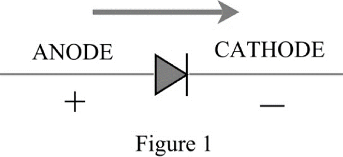
The diode operates like a swtich, when the diode is forward biased the current flows through it in one direction only that is from P terminal to N terminal. To reverse the diode the cathode is connected to P and anode to N, for ideal condition the diode do not conduct in reverse but there is a small amount of current through it that is called the leakage current.
The zener diode is the diode that can operate in the reverse biased and the region of operation in that case is called the zener region. The diode conducts when the diodes breaks down in the reverse direction known as avalanche.
Therefore, the zener diode is connected in the circuit in reverse polarity as compared to common junction diode.
Want to see more full solutions like this?
Chapter 58 Solutions
EBK 3N3-EBK: INDUSTRIAL MOTOR CONTROL


- PROBLEM 3.46 The solid cylindrical rod BC of length L = 600 mm is attached to the rigid lever AB of length a = 380 mm and to the support at C. When a 500 N force P is applied at A, design specifications require that the displacement of A not exceed 25 mm when a 500 N force P is applied at A For the material indicated determine the required diameter of the rod. Aluminium: Tall = 65 MPa, G = 27 GPa. Aarrow_forwardFind the equivalent mass of the rocker arm assembly with respect to the x coordinate. k₁ mi m2 k₁arrow_forward2. Figure below shows a U-tube manometer open at both ends and containing a column of liquid mercury of length l and specific weight y. Considering a small displacement x of the manometer meniscus from its equilibrium position (or datum), determine the equivalent spring constant associated with the restoring force. Datum Area, Aarrow_forward
- 1. The consequences of a head-on collision of two automobiles can be studied by considering the impact of the automobile on a barrier, as shown in figure below. Construct a mathematical model (i.e., draw the diagram) by considering the masses of the automobile body, engine, transmission, and suspension and the elasticity of the bumpers, radiator, sheet metal body, driveline, and engine mounts.arrow_forward3.) 15.40 – Collar B moves up at constant velocity vB = 1.5 m/s. Rod AB has length = 1.2 m. The incline is at angle = 25°. Compute an expression for the angular velocity of rod AB, ė and the velocity of end A of the rod (✓✓) as a function of v₂,1,0,0. Then compute numerical answers for ȧ & y_ with 0 = 50°.arrow_forward2.) 15.12 The assembly shown consists of the straight rod ABC which passes through and is welded to the grectangular plate DEFH. The assembly rotates about the axis AC with a constant angular velocity of 9 rad/s. Knowing that the motion when viewed from C is counterclockwise, determine the velocity and acceleration of corner F.arrow_forward
 Understanding Motor ControlsMechanical EngineeringISBN:9781337798686Author:Stephen L. HermanPublisher:Delmar Cengage Learning
 Refrigeration and Air Conditioning Technology (Mi...Mechanical EngineeringISBN:9781305578296Author:John Tomczyk, Eugene Silberstein, Bill Whitman, Bill JohnsonPublisher:Cengage Learning
 Electrical Transformers and Rotating MachinesMechanical EngineeringISBN:9781305494817Author:Stephen L. HermanPublisher:Cengage Learning
 Automotive Technology: A Systems Approach (MindTa...Mechanical EngineeringISBN:9781133612315Author:Jack Erjavec, Rob ThompsonPublisher:Cengage Learning