
Mechanics of Materials
10th Edition
ISBN: 9780134321158
Author: HIBBELER
Publisher: PEARSON
expand_more
expand_more
format_list_bulleted
Concept explainers
Videos
Textbook Question
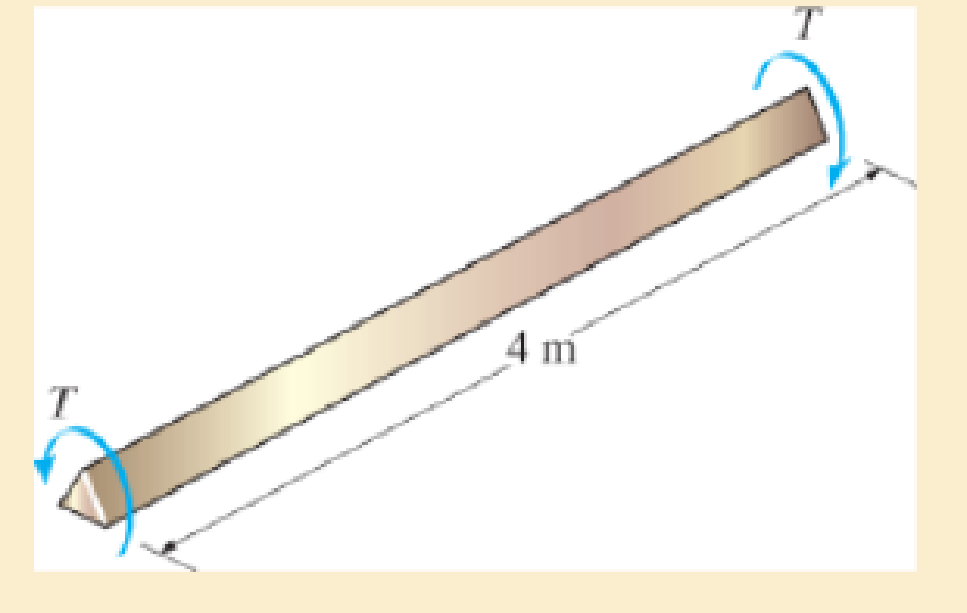
Chapter 5.7, Problem 5.95P
If the yield stress for brass is τY = 205 MPa, determine the maximum torque T to which it can be subjected so that the wire will not yield. If this torque is applied to the 4-m-long segment, determine the greatest angle of twist of one end of the wire relative to the other end that will not cause permanent damage to the wire. Gbr = 37 GPa.
Expert Solution & Answer
Want to see the full answer?
Check out a sample textbook solution
Students have asked these similar questions
Problem 13:
F₁ =
A
=250 N 30%
Determine the moment of each of the three forces about point B.
F₂ = 300 N
60°
2 m
-3 m
B
4 m
F3=500 N
3 kN
3 kN
1.8 kN/m
80 mm
B
300 mm
D
an
1.5 m-1.5 m--1.5 m-
PROBLEM 5.47
Using the method of Sec. 5.2, solve Prob. 5.16
PROBLEM 5.16 For the beam and loading shown, determine the
maximum normal stress due to bending on a transverse section at C.
300 mm
3 kN
3 kN
450 N-m
D
E
200 mm
300 mm
PROBLEM 5.12
Draw the shear and bending-moment diagrams for the beam and loading
shown, and determine the maximum absolute value (a) of the shear,
(b) of the bending moment.
Chapter 5 Solutions
Mechanics of Materials
Ch. 5.3 - Determine the internal torque at each section and...Ch. 5.3 - Determine the. internal torque at each section and...Ch. 5.3 - The solid and hollow shafts are each subjected to...Ch. 5.3 - The motor delivers 10 hp to the shaft. If it...Ch. 5.3 - The solid circular shaft is subjected to an...Ch. 5.3 - The hollow circular shaft is subjected to an...Ch. 5.3 - The shaft is hollow from A to B and solid from B...Ch. 5.3 - Determine the maximum shear stress in the...Ch. 5.3 - Determine the maximum shear stress in the shaft at...Ch. 5.3 - Determine the shear stress a: point A on the...
Ch. 5.3 - The solid 50-mm-diameter shaft is subjected to the...Ch. 5.3 - The gear motor can develop 3 hp when it turns at...Ch. 5.3 - The solid shaft of radius r is subjected to a...Ch. 5.3 - The solid shaft of radius r is subjected to a...Ch. 5.3 - A shaft is made of an aluminum alloy having an...Ch. 5.3 - The copper pipe has an outer diameter of 40 mm and...Ch. 5.3 - The copper pipe has an outer diameter of 2.50 in....Ch. 5.3 - The solid aluminum shaft has a diameter of 50 mm...Ch. 5.3 - The solid aluminum shaft has a diameter of 50 mm....Ch. 5.3 - The solid 30-mm-diameter shaft is used to transmit...Ch. 5.3 - The solid shaft is fixed to the support at C and...Ch. 5.3 - The link acts as part of the elevator control for...Ch. 5.3 - The assembly consists of two sections of...Ch. 5.3 - The shaft has an outer diameter of 100 mm and an...Ch. 5.3 - The shaft has an outer diameter of 100 mm and an...Ch. 5.3 - A steel tube having an outer diameter of 2.5 in....Ch. 5.3 - If the gears are subjected to the torques shown,...Ch. 5.3 - If the gears are subjected to the torques shown,...Ch. 5.3 - The rod has a diameter of 1 in. and a weight of 10...Ch. 5.3 - The rod has a diameter of 1 in. and a weight of 15...Ch. 5.3 - The copper pipe has an outer diameter of 3 in. and...Ch. 5.3 - The copper pipe has an outer diameter of 3 in. and...Ch. 5.3 - The 60-mm-diameter solid shaft is subjected to the...Ch. 5.3 - The 60-mm-diameter solid shaft is subjected to the...Ch. 5.3 - The solid shaft is subjected to the distributed...Ch. 5.3 - The 60-mm-diameter solid shaft is subjected to the...Ch. 5.3 - The solid shaft is subjected to the distributed...Ch. 5.3 - The pipe has an outer radius r0 and inner radius...Ch. 5.3 - The drive shaft AB of an automobile is made of a...Ch. 5.3 - The drive shaft AB of an automobile is to be...Ch. 5.3 - Prob. 5.29PCh. 5.3 - The motor delivers 50 hp while turning at a...Ch. 5.3 - The solid steel shaft AC has a diameter of 25 mm...Ch. 5.3 - The pump operates using the motor that has a power...Ch. 5.3 - The gear motor can develop 110 hp when it turns at...Ch. 5.3 - The gear motor can develop 110 hp when it turns at...Ch. 5.3 - The gear motor can develop 14 hp when it turns at...Ch. 5.3 - The gear motor can develop 2 hp when it turns at...Ch. 5.3 - The 6-hp reducer motor can turn at 1200 rev/min....Ch. 5.3 - The 6-hp reducer motor can turn at 1200 rev/min....Ch. 5.3 - Prob. 5.39PCh. 5.3 - Prob. 5.40PCh. 5.3 - The A-36 steel tubular shaft is 2 m long and has...Ch. 5.3 - Prob. 5.42PCh. 5.3 - The solid shaft has a linear taper from rA at one...Ch. 5.3 - The 1-in.-diameter bent rod is subjected to the...Ch. 5.3 - The 1-in.-diameter bent rod is subjected to the...Ch. 5.3 - A motor delivers 500 hp to the shaft, which is...Ch. 5.4 - The 60 mm-diameter steel shaft is subjected to the...Ch. 5.4 - Prob. 5.10FPCh. 5.4 - The hollow 6061-T6 aluminum shaft has an outer and...Ch. 5.4 - A series of gears are mounted on the...Ch. 5.4 - The 80-mm-diameter shaft is made of steel. If it...Ch. 5.4 - The 80-mm-diameter shaft is made of steel. If it...Ch. 5.4 - The propellers of a ship are connected to an A-36...Ch. 5.4 - Show that the maximum shear strain in the shaft is...Ch. 5.4 - Determine the angle of twist of end B with respect...Ch. 5.4 - Determine the absolute maximum shear stress in the...Ch. 5.4 - Determine the maximum allowable torque T. Also,...Ch. 5.4 - If the allowable shear stress is allow = 80 MPa,...Ch. 5.4 - Determine the angle of twist of the end A.Ch. 5.4 - If gear B supplies 15 kW of power, while gears A,...Ch. 5.4 - If the shaft is made of steel with the allowable...Ch. 5.4 - Prob. 5.56PCh. 5.4 - If the rotation of the 100-mm-diameter A-36 steel...Ch. 5.4 - If the rotation of the 100-mm-diameter A-36 steel...Ch. 5.4 - It has a diameter of 1 in. and is supported by...Ch. 5.4 - Prob. 5.60PCh. 5.4 - Determine the absolute maximum shear stress in the...Ch. 5.4 - If the rotation of the 100-mm-diameter A992 steel...Ch. 5.4 - If the mixer is connected to an A-36 steel tubular...Ch. 5.4 - If the mixer is connected to an A-36 steel tubular...Ch. 5.4 - Also, calculate the absolute maximum shear stress...Ch. 5.4 - When it is rotating at 80 rad/s. it transmits 32...Ch. 5.4 - It is required to transmit 35 kW of power from the...Ch. 5.4 - Determine the angle of twist at end A. The shear...Ch. 5.4 - If a torque of T = 50 N m is applied to the bolt...Ch. 5.4 - If a torque of T= 50N m is applied to the bolt...Ch. 5.4 - If the motor delivers 4 MW of power to the shaft...Ch. 5.4 - Determine the angle of twist at the free end A of...Ch. 5.4 - Prob. 5.73PCh. 5.4 - Prob. 5.74PCh. 5.4 - Determine the angle of twist at the free end A of...Ch. 5.4 - If the shaft is subjected to a torque T at its...Ch. 5.5 - Gst = 75 GPa.Ch. 5.5 - The A992 steel shaft has a diameter of 60 mm and...Ch. 5.5 - If the shaft is fixed at its ends A and B and...Ch. 5.5 - and a thickness of 0.125 in. The coupling on it at...Ch. 5.5 - The coupling on it at C is being tightened using...Ch. 5.5 - The shaft is made of L2 tool steel, has a diameter...Ch. 5.5 - The shaft is made of L2 tool steel, has a diameter...Ch. 5.5 - If the allowable shear stresses for the magnesium...Ch. 5.5 - If a torque of T = 5 kNm is applied to end A,...Ch. 5.5 - Each has a diameter of 25 mm and they are...Ch. 5.5 - Each has a diameter of 25 mm and they are...Ch. 5.5 - It is fixed at its ends and subjected to a torque...Ch. 5.5 - 5–89. Determine the absolute maximum shear stress...Ch. 5.5 - Each has a diameter of 1.5 in. and they are...Ch. 5.5 - The shaft is subjected to a torque of 800 lbft....Ch. 5.5 - The shaft is made of 2014-T6 aluminum alloy and is...Ch. 5.5 - The tapered shaft is confined by the fixed...Ch. 5.5 - Determine the reactions at the fixed supports A...Ch. 5.7 - If the yield stress for brass is Y = 205 MPa,...Ch. 5.7 - By what percentage is the shaft of circular cross...Ch. 5.7 - Prob. 5.97PCh. 5.7 - If it is subjected to the torsional loading,...Ch. 5.7 - Solve Prob.5-98 for the maximum shear stress...Ch. 5.7 - determine the maximum shear stress in the shaft....Ch. 5.7 - If the shaft has an equilateral triangle cross...Ch. 5.7 - by 2 in. square cross section, and it is subjected...Ch. 5.7 - is applied to the tube If the wall thickness is...Ch. 5.7 - If it is 2 m long, determine the maximum shear...Ch. 5.7 - Also, find the angle of twist of end B. The shaft...Ch. 5.7 - Also, find the corresponding angle of twist at end...Ch. 5.7 - If the solid shaft is made from red brass C83400...Ch. 5.7 - If the solid shaft is made from red brass C83400...Ch. 5.7 - The tube is 0.1 in. thick.Ch. 5.7 - Prob. 5.110PCh. 5.7 - Determine the average shear stress in the tube if...Ch. 5.7 - By what percentage is the torsional strength...Ch. 5.7 - Prob. 5.113PCh. 5.7 - Prob. 5.114PCh. 5.7 - If the allowable shear stress is allow = 8 ksi,...Ch. 5.7 - Prob. 5.116PCh. 5.7 - If the allowable shear stress is allow = 80 MPa,...Ch. 5.7 - If the applied torque is T = 50 Nm, determine the...Ch. 5.7 - If it is subjected to a torque of T = 40 Nm....Ch. 5.10 - If the transition between the cross sections has a...Ch. 5.10 - Prob. 5.121PCh. 5.10 - If the radius of the fillet weld connecting the...Ch. 5.10 - Prob. 5.123PCh. 5.10 - Determine the maximum shear stress in the shaft. A...Ch. 5.10 - Prob. 5.125PCh. 5.10 - Determine the radius of the elastic core produced...Ch. 5.10 - Assume that the material becomes fully plastic.Ch. 5.10 - diameter is subjected to a torque of 100 in.kip....Ch. 5.10 - Determine the torque T needed to form an elastic...Ch. 5.10 - Determine the torque applied to the shaft.Ch. 5.10 - Prob. 5.131PCh. 5.10 - Determine the ratio of the plastic torque Tp to...Ch. 5.10 - Determine the applied torque T, which subjects the...Ch. 5.10 - Determine the torque needed to just cause the...Ch. 5.10 - Determine the radius of its elastic core if it is...Ch. 5.10 - Plot the shear-stress distribution acting along a...Ch. 5.10 - If the material obeys a shear stress-strain...Ch. 5.10 - It is made of an elastic perfectly plastic...Ch. 5.10 - Prob. 5.139PCh. 5.10 - Prob. 5.140PCh. 5.10 - is made from an elastic perfectly plastic material...Ch. 5.10 - Prob. 5.142PCh. 5.10 - If the materials have the diagrams shown,...Ch. 5.10 - Determine the torque required to cause a maximum...Ch. 5 - The shaft is made of A992 steel and has an...Ch. 5 - The shaft is made of A992 steel and has an...Ch. 5 - Determine the shear stress at the mean radius p =...Ch. 5 - If the thickness of its 2014-T6-aluminum skin is...Ch. 5 - Determine which shaft geometry will resist the...Ch. 5 - If couple forces P = 3 kip are applied to the...Ch. 5 - If the allowable shear stress for the aluminum is...Ch. 5 - Determine the angle of twist of its end A if it is...Ch. 5 - This motion is caused by the unequal belt tensions...
Knowledge Booster


Learn more about
Need a deep-dive on the concept behind this application? Look no further. Learn more about this topic, mechanical-engineering and related others by exploring similar questions and additional content below.Similar questions
- CORRECT AND DETAILED SOLUTION WITH FBD ONLY. I WILL UPVOTE THANK YOU. CORRECT ANSWER IS ALREADY PROVIDED. I REALLY NEED FBD. The cantilevered spandrel beam shown whose depth tapers from d1 to d2, has a constant width of 120mm. It carries a triangularly distributed end reaction.Given: d1 = 600 mm, d2 = 120 mm, L = 1 m, w = 100 kN/m1. Calculate the maximum flexural stress at the support, in kN-m.2. Determine the distance (m), from the free end, of the section with maximum flexural stress.3. Determine the maximum flexural stress in the beam, in MPa.ANSWERS: (1) 4.630 MPa; (2) 905.8688 m; (3) 4.65 MPaarrow_forwardCORRECT AND DETAILED SOLUTION WITH FBD ONLY. I WILL UPVOTE THANK YOU. CORRECT ANSWER IS ALREADY PROVIDED. I REALLY NEED FBD A concrete wall retains water as shown. Assume that the wall is fixed at the base. Given: H = 3 m, t = 0.5m, Concrete unit weight = 23 kN/m3Unit weight of water = 9.81 kN/m3(Hint: The pressure of water is linearly increasing from the surface to the bottom with intensity 9.81d.)1. Find the maximum compressive stress (MPa) at the base of the wall if the water reaches the top.2. If the maximum compressive stress at the base of the wall is not to exceed 0.40 MPa, what is the maximum allowable depth(m) of the water?3. If the tensile stress at the base is zero, what is the maximum allowable depth (m) of the water?ANSWERS: (1) 1.13 MPa, (2) 2.0 m, (3) 1.20 marrow_forwardCORRECT AND DETAILED SOLUTION WITH FBD ONLY. I WILL UPVOTE THANK YOU. CORRECT ANSWER IS ALREADY PROVIDED. I NEED FBD A short plate is attached to the center of the shaft as shown. The bottom of the shaft is fixed to the ground.Given: a = 75 mm, h = 125 mm, D = 38 mmP1 = 24 kN, P2 = 28 kN1. Calculate the maximum torsional stress in the shaft, in MPa.2. Calculate the maximum flexural stress in the shaft, in MPa.3. Calculate the maximum horizontal shear stress in the shaft, in MPa.ANSWERS: (1) 167.07 MPa; (2) 679.77 MPa; (3) 28.22 MPaarrow_forward
- CORRECT AND DETAILED SOLUTION WITH FBD ONLY. I WILL UPVOTE THANK YOU. CORRECT ANSWER IS ALREADY PROVIDED. I REALLY NEED FBD. The roof truss shown carries roof loads, where P = 10 kN. The truss is consisting of circular arcs top andbottom chords with radii R + h and R, respectively.Given: h = 1.2 m, R = 10 m, s = 2 m.Allowable member stresses:Tension = 250 MPaCompression = 180 MPa1. If member KL has square section, determine the minimum dimension (mm).2. If member KL has circular section, determine the minimum diameter (mm).3. If member GH has circular section, determine the minimum diameter (mm).ANSWERS: (1) 31.73 mm; (2) 35.81 mm; (3) 18.49 mmarrow_forwardPROBLEM 3.23 3.23 Under normal operating condi- tions a motor exerts a torque of magnitude TF at F. The shafts are made of a steel for which the allowable shearing stress is 82 MPa and have diameters of dCDE=24 mm and dFGH = 20 mm. Knowing that rp = 165 mm and rg114 mm, deter- mine the largest torque TF which may be exerted at F. TF F rG- rp B CH TE Earrow_forward1. (16%) (a) If a ductile material fails under pure torsion, please explain the failure mode and describe the observed plane of failure. (b) Suppose a prismatic beam is subjected to equal and opposite couples as shown in Fig. 1. Please sketch the deformation and the stress distribution of the cross section. M M Fig. 1 (c) Describe the definition of the neutral axis. (d) Describe the definition of the modular ratio.arrow_forward
- using the theorem of three moments, find all the moments, I only need concise calculations with minimal explanations. The correct answers are provided at the bottomarrow_forwardMechanics of materialsarrow_forwardusing the theorem of three moments, find all the moments, I need concise calculations onlyarrow_forward
arrow_back_ios
SEE MORE QUESTIONS
arrow_forward_ios
Recommended textbooks for you
 Elements Of ElectromagneticsMechanical EngineeringISBN:9780190698614Author:Sadiku, Matthew N. O.Publisher:Oxford University Press
 Mechanics of Materials (10th Edition)Mechanical EngineeringISBN:9780134319650Author:Russell C. HibbelerPublisher:PEARSON
 Thermodynamics: An Engineering ApproachMechanical EngineeringISBN:9781259822674Author:Yunus A. Cengel Dr., Michael A. BolesPublisher:McGraw-Hill Education
 Control Systems EngineeringMechanical EngineeringISBN:9781118170519Author:Norman S. NisePublisher:WILEY
 Mechanics of Materials (MindTap Course List)Mechanical EngineeringISBN:9781337093347Author:Barry J. Goodno, James M. GerePublisher:Cengage Learning
 Engineering Mechanics: StaticsMechanical EngineeringISBN:9781118807330Author:James L. Meriam, L. G. Kraige, J. N. BoltonPublisher:WILEY
Elements Of Electromagnetics
Mechanical Engineering
ISBN:9780190698614
Author:Sadiku, Matthew N. O.
Publisher:Oxford University Press
Mechanics of Materials (10th Edition)
Mechanical Engineering
ISBN:9780134319650
Author:Russell C. Hibbeler
Publisher:PEARSON
Thermodynamics: An Engineering Approach
Mechanical Engineering
ISBN:9781259822674
Author:Yunus A. Cengel Dr., Michael A. Boles
Publisher:McGraw-Hill Education
Control Systems Engineering
Mechanical Engineering
ISBN:9781118170519
Author:Norman S. Nise
Publisher:WILEY
Mechanics of Materials (MindTap Course List)
Mechanical Engineering
ISBN:9781337093347
Author:Barry J. Goodno, James M. Gere
Publisher:Cengage Learning
Engineering Mechanics: Statics
Mechanical Engineering
ISBN:9781118807330
Author:James L. Meriam, L. G. Kraige, J. N. Bolton
Publisher:WILEY
Understanding Torsion; Author: The Efficient Engineer;https://www.youtube.com/watch?v=1YTKedLQOa0;License: Standard YouTube License, CC-BY