
MECHANICS OF MATERIALS-TEXT
9th Edition
ISBN: 2810014920922
Author: HIBBELER
Publisher: PEARSON
expand_more
expand_more
format_list_bulleted
Videos
Textbook Question
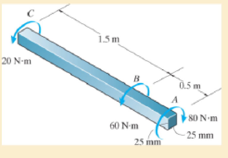
Chapter 5.7, Problem 5.104P
If it is 2 m long, determine the maximum shear stress in the bar and the rotation of one end relative to the other end.
Expert Solution & Answer
Want to see the full answer?
Check out a sample textbook solution
Students have asked these similar questions
Please solve this problem as soon as possible My ID# 016948724
The gears shown in the figure have a diametral pitch of 2 teeth per inch and a 20° pressure angle.
The pinion rotates at 1800 rev/min clockwise and transmits 200 hp through the idler pair to gear
5 on shaft c. What forces do gears 3 and 4 transmit to the idler shaft?
TS
I
y
18T
32T
This
a
12
x
18T
C
48T
5
Question 1. Draw 3 teeth for the following pinion and gear respectively. The teeth
should be drawn near the pressure line so that the teeth from the pinion should
mesh those of the gear. Drawing scale (1:1). Either a precise hand drawing or
CAD drawing is acceptable. Draw all the trajectories of the involute lines and the
circles.
Specification: 18tooth pinion and 30tooth gear. Diameter pitch=P=6 teeth /inch.
Pressure angle:20°, 1/P for addendum (a) and 1.25/P for dedendum (b). For fillet,
c=b-a.
Chapter 5 Solutions
MECHANICS OF MATERIALS-TEXT
Ch. 5.3 - Determine the internal torque at each section and...Ch. 5.3 - Determine the. internal torque at each section and...Ch. 5.3 - The solid and hollow shafts are each subjected to...Ch. 5.3 - The motor delivers 10 hp to the shaft. If it...Ch. 5.3 - The solid circular shaft is subjected to an...Ch. 5.3 - The hollow circular shaft is subjected to an...Ch. 5.3 - The shaft is hollow from A to B and solid from B...Ch. 5.3 - Determine the maximum shear stress in the...Ch. 5.3 - Determine the maximum shear stress in the shaft at...Ch. 5.3 - Determine the shear stress a: point A on the...
Ch. 5.3 - The solid 50-mm-diameter shaft is subjected to the...Ch. 5.3 - The gear motor can develop 3 hp when it turns at...Ch. 5.3 - The solid shaft of radius r is subjected to a...Ch. 5.3 - The solid shaft of radius r is subjected to a...Ch. 5.3 - 5-3. The solid shaft is fixed to the support at C...Ch. 5.3 - The copper pipe has an outer diameter of 40 mm and...Ch. 5.3 - The copper pipe has an outer diameter of 2.50 in....Ch. 5.3 - Prob. 5.6PCh. 5.3 - Prob. 5.7PCh. 5.3 - The solid 30-mm-diameter shaft is used to transmit...Ch. 5.3 - The solid shaft is fixed to the support at C and...Ch. 5.3 - Prob. 5.10PCh. 5.3 - The assembly consists of two sections of...Ch. 5.3 - Prob. 5.12PCh. 5.3 - 5-13. If The tubular shaft is made from material...Ch. 5.3 - A steel tube having an outer diameter of 2.5 in....Ch. 5.3 - Prob. 5.15PCh. 5.3 - Prob. 5.16PCh. 5.3 - The rod has a diameter of 1 in. and a weight of 10...Ch. 5.3 - The rod has a diameter of 1 in. and a weight of 15...Ch. 5.3 - 5-19. The shaft consists of solid 80-mm-diameter...Ch. 5.3 - Prob. 5.20PCh. 5.3 - 5-21. If the 40-mm-diameter rod is subjected to a...Ch. 5.3 - Prob. 5.22PCh. 5.3 - Prob. 5.23PCh. 5.3 - Prob. 5.24PCh. 5.3 - Prob. 5.25PCh. 5.3 - Prob. 5.26PCh. 5.3 - Prob. 5.27PCh. 5.3 - Prob. 5.28PCh. 5.3 - Prob. 5.29PCh. 5.3 - Prob. 5.30PCh. 5.3 - The solid steel shaft AC has a diameter of 25 mm...Ch. 5.3 - The pump operates using the motor that has a power...Ch. 5.3 - Prob. 5.33PCh. 5.3 - Prob. 5.34PCh. 5.3 - Prob. 5.35PCh. 5.3 - Prob. 5.36PCh. 5.3 - Prob. 5.37PCh. 5.3 - Prob. 5.38PCh. 5.3 - Prob. 5.39PCh. 5.3 - Prob. 5.40PCh. 5.3 - The A-36 steel tubular shaft is 2 m long and has...Ch. 5.3 - Prob. 5.42PCh. 5.3 - The solid shaft has a linear taper from rA at one...Ch. 5.3 - *5-44. The rod has a diameter of 0.5 in. and...Ch. 5.3 - 5-45. Solve Prob. 5-44 for the maximum torsional...Ch. 5.3 - A motor delivers 500 hp to the shaft, which is...Ch. 5.4 - The 60 mm-diameter steel shaft is subjected to the...Ch. 5.4 - Prob. 5.10FPCh. 5.4 - The hollow 6061-T6 aluminum shaft has an outer and...Ch. 5.4 - A series of gears are mounted on the...Ch. 5.4 - The 80-mm-diameter shaft is made of steel. If it...Ch. 5.4 - The 80-mm-diameter shaft is made of steel. If it...Ch. 5.4 - The propellers of a ship are connected to an A-36...Ch. 5.4 - Show that the maximum shear strain in the shaft is...Ch. 5.4 - 5-49. The A-36 steel axle is made from tubes AB...Ch. 5.4 - Prob. 5.50PCh. 5.4 - Determine the maximum allowable torque T. Also,...Ch. 5.4 - If the allowable shear stress is allow = 80 MPa,...Ch. 5.4 - Prob. 5.53PCh. 5.4 - If gear B supplies 15 kW of power, while gears A,...Ch. 5.4 - If the shaft is made of steel with the allowable...Ch. 5.4 - *5-56. The A-36 steel axle is made from tubes AB...Ch. 5.4 - If the rotation of the 100-mm-diameter A-36 steel...Ch. 5.4 - If the rotation of the 100-mm-diameter A-36 steel...Ch. 5.4 - It has a diameter of 1 in. and is supported by...Ch. 5.4 - Prob. 5.60PCh. 5.4 - Prob. 5.61PCh. 5.4 - Prob. 5.62PCh. 5.4 - Prob. 5.63PCh. 5.4 - Prob. 5.64PCh. 5.4 - Prob. 5.65PCh. 5.4 - When it is rotating at 80 rad/s. it transmits 32...Ch. 5.4 - It is required to transmit 35 kW of power from the...Ch. 5.4 - Prob. 5.68PCh. 5.4 - If a torque of T = 50 N m is applied to the bolt...Ch. 5.4 - If a torque of T= 50N m is applied to the bolt...Ch. 5.4 - Prob. 5.72PCh. 5.4 - If the shaft is subjected to a torque T at its...Ch. 5.4 - Prob. 5.74PCh. 5.4 - Prob. 5.75PCh. 5.4 - *5-76. A cylindrical spring consists of a rubber...Ch. 5.5 - Gst = 75 GPa.Ch. 5.5 - The A992 steel shaft has a diameter of 60 mm and...Ch. 5.5 - If the shaft is fixed at its ends A and B and...Ch. 5.5 - Prob. 5.80PCh. 5.5 - Prob. 5.81PCh. 5.5 - 5-82. The shaft is made from a solid steel section...Ch. 5.5 - 5-83. The motor A develops a torque at gear B of...Ch. 5.5 - If the allowable shear stresses for the magnesium...Ch. 5.5 - If a torque of T = 5 kNm is applied to end A,...Ch. 5.5 - Each has a diameter of 25 mm and they are...Ch. 5.5 - Each has a diameter of 25 mm and they are...Ch. 5.5 - It is fixed at its ends and subjected to a torque...Ch. 5.5 - 5–89. Determine the absolute maximum shear stress...Ch. 5.5 - The shaft is subjected to a torque of 800 lbft....Ch. 5.5 - Prob. 5.91PCh. 5.5 - The shaft is made of 2014-T6 aluminum alloy and is...Ch. 5.5 - The tapered shaft is confined by the fixed...Ch. 5.5 - Determine the reactions at the fixed supports A...Ch. 5.7 - 5-95. The aluminum rod has a square cross section...Ch. 5.7 - Prob. 5.96PCh. 5.7 - Prob. 5.97PCh. 5.7 - If it is subjected to the torsional loading,...Ch. 5.7 - Solve Prob.5-98 for the maximum shear stress...Ch. 5.7 - determine the maximum shear stress in the shaft....Ch. 5.7 - If the shaft has an equilateral triangle cross...Ch. 5.7 - 5-102. The aluminum strut is fixed between the two...Ch. 5.7 - is applied to the tube If the wall thickness is...Ch. 5.7 - If it is 2 m long, determine the maximum shear...Ch. 5.7 - Also, find the angle of twist of end B. The shaft...Ch. 5.7 - Also, find the corresponding angle of twist at end...Ch. 5.7 - If the solid shaft is made from red brass C83400...Ch. 5.7 - If the solid shaft is made from red brass C83400...Ch. 5.7 - The tube is 0.1 in. thick.Ch. 5.7 - 5-110. For a given maximum average shear stress,...Ch. 5.7 - 5-111. A torque T is applied to two tubes having...Ch. 5.7 - By what percentage is the torsional strength...Ch. 5.7 - 5-113. Determine the constant thickness of the...Ch. 5.7 - 5-114. Determine the torque T that can be applied...Ch. 5.7 - If the allowable shear stress is allow = 8 ksi,...Ch. 5.7 - *5-116. The tube is made of plastic, is 5 mm...Ch. 5.7 - 5–117. The mean dimensions of the cross section of...Ch. 5.7 - 5–118. The mean dimensions of the cross section of...Ch. 5.7 - If it is subjected to a torque of T = 40 Nm....Ch. 5.10 - If the transition between the cross sections has a...Ch. 5.10 - 5–121. The step shaft is to be designed to rotate...Ch. 5.10 - Prob. 5.122PCh. 5.10 - 5–123. The transition at the cross sections of the...Ch. 5.10 - *5–124. The steel used for the step shaft has an...Ch. 5.10 - 5–125. The step shaft is subjected to a torque of...Ch. 5.10 - Determine the radius of the elastic core produced...Ch. 5.10 - Assume that the material becomes fully plastic.Ch. 5.10 - diameter is subjected to a torque of 100 in.kip....Ch. 5.10 - Determine the torque T needed to form an elastic...Ch. 5.10 - Determine the torque applied to the shaft.Ch. 5.10 - 5–131. An 80-mm-diameter solid circular shaft is...Ch. 5.10 - Determine the ratio of the plastic torque Tp to...Ch. 5.10 - 5–133. If the step shaft is elastic-plastic as...Ch. 5.10 - 5–134. The solid shaft is made from an...Ch. 5.10 - 5–135. A 1.5-in.-diameter shaft is made from an...Ch. 5.10 - *5–136. The tubular shaft is made of a...Ch. 5.10 - 5–137. The shaft is made from a strain-hardening...Ch. 5.10 - 5–138. The tube is made of elastic-perfectly...Ch. 5.10 - Determine the torque required to cause a maximum...Ch. 5.10 - *5–140. The 2-m-long tube is made of an...Ch. 5.10 - is made from an elastic perfectly plastic material...Ch. 5.10 - 5–142. The 2-m-long lube is made from an...Ch. 5 - The shaft is made of A992 steel and has an...Ch. 5 - The shaft is made of A992 steel and has an...Ch. 5 - Determine the shear stress at the mean radius p =...Ch. 5 - If the thickness of its 2014-T6-aluminum skin is...Ch. 5 - Determine which shaft geometry will resist the...Ch. 5 - If couple forces P = 3 kip are applied to the...Ch. 5 - If the allowable shear stress for the aluminum is...Ch. 5 - Determine the angle of twist of its end A if it is...Ch. 5 - This motion is caused by the unequal belt tensions...
Knowledge Booster


Learn more about
Need a deep-dive on the concept behind this application? Look no further. Learn more about this topic, mechanical-engineering and related others by exploring similar questions and additional content below.Similar questions
- 5. The figure shows a gear train. There is no friction at the bearings except for the gear tooth forces. The material of the milled gears is steel having a Brinell hardness of 170. The input shaft speed (n2) is 800 rpm. The face width and the contact angle for all gears are 1 in and 20° respectively. In this gear set, the endurance limit (Se) is 15 kpsi and nd (design factor) is 2. (a) Find the revolution speed of gear 5. (b) Determine whether each gear satisfies the design factor of 2.0 for bending fatigue. (c) Determine whether each gear satisfies the design factor of 2.0 for surface fatigue (contact stress). (d) According to the computation results of the questions (b) and (c), explain the possible failure mechanisms for each gear. N4=28 800rpm N₁=43 N5=34 N₂=14 P(diameteral pitch)=8 for all gears Coupled to 2.5hp motorarrow_forward1. The rotating steel shaft is simply supported by bearings at points of B and C, and is driven by a spur gear at D, which has a 6-in pitch diameter. The force F from the drive gear acts at a pressure angle of 20°. The shaft transmits a torque to point A of TA =3000 lbĘ in. The shaft is machined from steel with Sy=60kpsi and Sut=80 kpsi. (1) Draw a shear force diagram and a bending moment diagram by F. According to your analysis, where is the point of interest to evaluate the safety factor among A, B, C, and D? Describe the reason. (Hint: To find F, the torque Tд is generated by the tangential force of F (i.e. Ftangential-Fcos20°) When n=2.5, K=1.8, and K₁ =1.3, determine the diameter of the shaft based on (2) static analysis using DE theory (note that fatigue stress concentration factors need to be used for this question because the loading condition is fatigue) and (3) a fatigue analysis using modified Goodman. Note) A standard diameter is not required for the questions. 10 in Darrow_forward3 N2=28 P(diametral pitch)=8 for all gears Coupled to 25 hp motor N3=34 Full depth spur gears with pressure angle=20° N₂=2000 rpm (1) Compute the circular pitch, the center-to-center distance, and base circle radii. (2) Draw the free body diagram of gear 3 and show all the forces and the torque. (3) In mounting gears, the center-to-center distance was reduced by 0.1 inch. Calculate the new values of center-to-center distance, pressure angle, base circle radii, and pitch circle diameters. (4)What is the new tangential and radial forces for gear 3? (5) Under the new center to center distance, is the contact ratio (mc) increasing or decreasing?arrow_forward
- 2. A flat belt drive consists of two 4-ft diameter cast-iron pulleys spaced 16 ft apart. A power of 60 hp is transmitted by a pulley whose speed is 380 rev/min. Use a service factor (Ks) pf 1.1 and a design factor 1.0. The width of the polyamide A-3 belt is 6 in. Use CD=1. Answer the following questions. (1) What is the total length of the belt according to the given geometry? (2) Find the centrifugal force (Fc) applied to the belt. (3) What is the transmitted torque through the pulley system given 60hp? (4) Using the allowable tension, find the force (F₁) on the tight side. What is the tension at the loose side (F2) and the initial tension (F.)? (5) Using the forces, estimate the developed friction coefficient (f) (6) Based on the forces and the given rotational speed, rate the pulley set. In other words, what is the horse power that can be transmitted by the pulley system? (7) To reduce the applied tension on the tight side, the friction coefficient is increased to 0.75. Find out the…arrow_forwardThe tooth numbers for the gear train illustrated are N₂ = 24, N3 = 18, №4 = 30, №6 = 36, and N₁ = 54. Gear 7 is fixed. If shaft b is turned through 5 revolutions, how many turns will shaft a make? a 5 [6] barrow_forwardCE-112 please solve this problem step by step and give me the correct answerarrow_forward
- CE-112 please solve this problem step by step and give me the correct answerarrow_forwardCE-112 solve this problem step by step and give me the correct answer pleasearrow_forwardPlease do not use any AI tools to solve this question. I need a fully manual, step-by-step solution with clear explanations, as if it were done by a human tutor. No AI-generated responses, please.arrow_forward
- Please do not use any AI tools to solve this question. I need a fully manual, step-by-step solution with clear explanations, as if it were done by a human tutor. No AI-generated responses, please.arrow_forwardCE-112 please solve this problem step by step and give me the correct answerarrow_forwardCE-112 please solve this problem step by step and give me the correct asnwerarrow_forward
arrow_back_ios
SEE MORE QUESTIONS
arrow_forward_ios
Recommended textbooks for you
 International Edition---engineering Mechanics: St...Mechanical EngineeringISBN:9781305501607Author:Andrew Pytel And Jaan KiusalaasPublisher:CENGAGE L
 Mechanics of Materials (MindTap Course List)Mechanical EngineeringISBN:9781337093347Author:Barry J. Goodno, James M. GerePublisher:Cengage Learning
 Principles of Heat Transfer (Activate Learning wi...Mechanical EngineeringISBN:9781305387102Author:Kreith, Frank; Manglik, Raj M.Publisher:Cengage Learning
International Edition---engineering Mechanics: St...
Mechanical Engineering
ISBN:9781305501607
Author:Andrew Pytel And Jaan Kiusalaas
Publisher:CENGAGE L
Mechanics of Materials (MindTap Course List)
Mechanical Engineering
ISBN:9781337093347
Author:Barry J. Goodno, James M. Gere
Publisher:Cengage Learning
Principles of Heat Transfer (Activate Learning wi...
Mechanical Engineering
ISBN:9781305387102
Author:Kreith, Frank; Manglik, Raj M.
Publisher:Cengage Learning
Everything About TRANSVERSE SHEAR in 10 Minutes!! - Mechanics of Materials; Author: Less Boring Lectures;https://www.youtube.com/watch?v=4x0E9yvzfCM;License: Standard Youtube License