
Engineering Mechanics: Statics & Dynamics (14th Edition)
14th Edition
ISBN: 9780133915426
Author: Russell C. Hibbeler
Publisher: PEARSON
expand_more
expand_more
format_list_bulleted
Concept explainers
Videos
Textbook Question
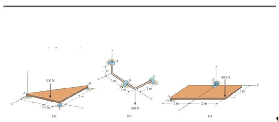
Chapter 5.7, Problem 2PP
Draw the free-body diagram of each object.
Expert Solution & Answer
Want to see the full answer?
Check out a sample textbook solution
Students have asked these similar questions
CORRECT AND DETAILED SOLUTION WITH FBD ONLY. I WILL UPVOTE THANK YOU. CORRECT ANSWER IS ALREADY PROVIDED. I REALLY NEED FBD.
The cantilevered spandrel beam shown whose depth tapers from d1 to d2, has a constant width of 120mm. It carries a triangularly distributed end reaction.Given: d1 = 600 mm, d2 = 120 mm, L = 1 m, w = 100 kN/m1. Calculate the maximum flexural stress at the support, in kN-m.2. Determine the distance (m), from the free end, of the section with maximum flexural stress.3. Determine the maximum flexural stress in the beam, in MPa.ANSWERS: (1) 4.630 MPa; (2) 905.8688 m; (3) 4.65 MPa
CORRECT AND DETAILED SOLUTION WITH FBD ONLY. I WILL UPVOTE THANK YOU. CORRECT ANSWER IS ALREADY PROVIDED. I REALLY NEED FBD
A concrete wall retains water as shown. Assume that the wall is fixed at the base. Given: H = 3 m, t = 0.5m, Concrete unit weight = 23 kN/m3Unit weight of water = 9.81 kN/m3(Hint: The pressure of water is linearly increasing from the surface to the bottom with intensity 9.81d.)1. Find the maximum compressive stress (MPa) at the base of the wall if the water reaches the top.2. If the maximum compressive stress at the base of the wall is not to exceed 0.40 MPa, what is the maximum allowable depth(m) of the water?3. If the tensile stress at the base is zero, what is the maximum allowable depth (m) of the water?ANSWERS: (1) 1.13 MPa, (2) 2.0 m, (3) 1.20 m
CORRECT AND DETAILED SOLUTION WITH FBD ONLY. I WILL UPVOTE THANK YOU. CORRECT ANSWER IS ALREADY PROVIDED. I NEED FBD
A short plate is attached to the center of the shaft as shown. The bottom of the shaft is fixed to the ground.Given: a = 75 mm, h = 125 mm, D = 38 mmP1 = 24 kN, P2 = 28 kN1. Calculate the maximum torsional stress in the shaft, in MPa.2. Calculate the maximum flexural stress in the shaft, in MPa.3. Calculate the maximum horizontal shear stress in the shaft, in MPa.ANSWERS: (1) 167.07 MPa; (2) 679.77 MPa; (3) 28.22 MPa
Chapter 5 Solutions
Engineering Mechanics: Statics & Dynamics (14th Edition)
Ch. 5.2 - Draw the free-body diagram for the following...Ch. 5.2 - Draw the free-body diagram for the following...Ch. 5.2 - Draw the free-body diagram for the following...Ch. 5.2 - Draw the free-body diagram for the following...Ch. 5.2 - Draw the free-body diagram for the following...Ch. 5.2 - Draw the free-body diagram for the following...Ch. 5.2 - Draw the free-body diagram for the following...Ch. 5.2 - Draw the free-body diagram for the following...Ch. 5.2 - Draw the free-body diagram for the following...Ch. 5.4 - Draw the free body diagram of each object. Prob....
Ch. 5.4 - Determine the horizontal and vertical components...Ch. 5.4 - Determine the horizontal and vertical components...Ch. 5.4 - The truss is supported by a pin at A and a roller...Ch. 5.4 - Prob. 4FPCh. 5.4 - The 25 kg bar has a center of mass at G. If it is...Ch. 5.4 - Prob. 6FPCh. 5.4 - Prob. 10PCh. 5.4 - Determine the reactions at the supports. Prob....Ch. 5.4 - Determine the horizontal and vertical components...Ch. 5.4 - Determine the reactions at the supports. Prob....Ch. 5.4 - Determine the reactions at the supports. Prob....Ch. 5.4 - Prob. 15PCh. 5.4 - Determine the tension in the cable and the...Ch. 5.4 - Prob. 17PCh. 5.4 - Determine the components of reaction at the...Ch. 5.4 - The man has a weight W and stands at the center of...Ch. 5.4 - A uniform glass rod having a length L is placed in...Ch. 5.4 - Prob. 21PCh. 5.4 - If the intensity of the distributed load acting on...Ch. 5.4 - Prob. 23PCh. 5.4 - Prob. 24PCh. 5.4 - Prob. 25PCh. 5.4 - The mobile crane is symmetrically supported by two...Ch. 5.4 - Prob. 27PCh. 5.4 - Prob. 28PCh. 5.4 - Determine the force P needed to pull the 50-kg...Ch. 5.4 - Prob. 30PCh. 5.4 - Prob. 31PCh. 5.4 - Determine the magnitude of force at the pin A and...Ch. 5.4 - The dimensions of a jib crane, which is...Ch. 5.4 - Prob. 34PCh. 5.4 - The smooth pipe rests against the opening at the...Ch. 5.4 - Prob. 36PCh. 5.4 - The cantilevered jib crane is used to support the...Ch. 5.4 - Prob. 38PCh. 5.4 - Prob. 39PCh. 5.4 - Determine the stiffness k of each spring so that...Ch. 5.4 - The bulk head AD Is subjected to both water and...Ch. 5.4 - The boom supports the two vertical loads. Neglect...Ch. 5.4 - Prob. 43PCh. 5.4 - The 10-kg uniform rod is pinned at end A. If It is...Ch. 5.4 - Prob. 45PCh. 5.4 - Prob. 46PCh. 5.4 - Prob. 47PCh. 5.4 - Prob. 48PCh. 5.4 - The rigid metal strip of negligible weight is used...Ch. 5.4 - Prob. 50PCh. 5.4 - Prob. 51PCh. 5.4 - Prob. 52PCh. 5.4 - Prob. 53PCh. 5.4 - Prob. 54PCh. 5.4 - The uniform rod has a length I and weight W. It is...Ch. 5.4 - Prob. 56PCh. 5.4 - Prob. 57PCh. 5.4 - Prob. 58PCh. 5.4 - The rod supports a weight of 200 lb and is pinned...Ch. 5.4 - Prob. 60PCh. 5.4 - Prob. 61PCh. 5.4 - The man attempts to pull the tour wheeler up the...Ch. 5.4 - Where is the best place to arrange most of the...Ch. 5.7 - Draw the free-body diagram of each object.Ch. 5.7 - In each case, write the moment equations about the...Ch. 5.7 - Prob. 7FPCh. 5.7 - Prob. 8FPCh. 5.7 - Prob. 9FPCh. 5.7 - Determine the support reactions at the smooth...Ch. 5.7 - Prob. 11FPCh. 5.7 - Determine the components of reaction that the...Ch. 5.7 - The uniform loads has a mass of 600 kg and is...Ch. 5.7 - Due to equal distribution of fuel in the wing...Ch. 5.7 - Prob. 5-63 5-64. Determine the components of...Ch. 5.7 - Prob. 65PCh. 5.7 - The smooth uniform rod AB is supported by a...Ch. 5.7 - The uniform concrete slab has a mass of 2400 kg....Ch. 5.7 - The 100-lb door has its center of gravity at G....Ch. 5.7 - Determine me tension in each cable and the...Ch. 5.7 - The stiff-leg derrick used on ships is supported...Ch. 5.7 - Determine the components of reaction at the...Ch. 5.7 - Determine the components of reaction at the...Ch. 5.7 - The bent rod is supported at A, B, and C by smooth...Ch. 5.7 - The bent rod is supported at A, B, and C by smooth...Ch. 5.7 - Prob. 75PCh. 5.7 - Prob. 76PCh. 5.7 - The member is supported by a square rod which fits...Ch. 5.7 - Prob. 78PCh. 5.7 - Prob. 79PCh. 5.7 - The bar AB is supported by two smooth collars. At...Ch. 5.7 - Prob. 81PCh. 5.7 - Prob. 82PCh. 5.7 - Prob. 83PCh. 5.7 - Both pulleys are fixed to the shaft and as the...Ch. 5.7 - Member AB is supported by a cable BC and at A by a...Ch. 5.7 - If the roller at 8 can sustain a maximum load of 3...Ch. 5.7 - Determine the reactions at the supports A and B...Ch. 5.7 - Prob. 3RPCh. 5.7 - Prob. 4RPCh. 5.7 - Determine the x, y, z components of reaction at...Ch. 5.7 - Prob. 6RPCh. 5.7 - Determine the x, y, z components of reaction at...Ch. 5.7 - Determine the x and z components of reaction at...
Knowledge Booster


Learn more about
Need a deep-dive on the concept behind this application? Look no further. Learn more about this topic, mechanical-engineering and related others by exploring similar questions and additional content below.Similar questions
- CORRECT AND DETAILED SOLUTION WITH FBD ONLY. I WILL UPVOTE THANK YOU. CORRECT ANSWER IS ALREADY PROVIDED. I REALLY NEED FBD. The roof truss shown carries roof loads, where P = 10 kN. The truss is consisting of circular arcs top andbottom chords with radii R + h and R, respectively.Given: h = 1.2 m, R = 10 m, s = 2 m.Allowable member stresses:Tension = 250 MPaCompression = 180 MPa1. If member KL has square section, determine the minimum dimension (mm).2. If member KL has circular section, determine the minimum diameter (mm).3. If member GH has circular section, determine the minimum diameter (mm).ANSWERS: (1) 31.73 mm; (2) 35.81 mm; (3) 18.49 mmarrow_forwardPROBLEM 3.23 3.23 Under normal operating condi- tions a motor exerts a torque of magnitude TF at F. The shafts are made of a steel for which the allowable shearing stress is 82 MPa and have diameters of dCDE=24 mm and dFGH = 20 mm. Knowing that rp = 165 mm and rg114 mm, deter- mine the largest torque TF which may be exerted at F. TF F rG- rp B CH TE Earrow_forward1. (16%) (a) If a ductile material fails under pure torsion, please explain the failure mode and describe the observed plane of failure. (b) Suppose a prismatic beam is subjected to equal and opposite couples as shown in Fig. 1. Please sketch the deformation and the stress distribution of the cross section. M M Fig. 1 (c) Describe the definition of the neutral axis. (d) Describe the definition of the modular ratio.arrow_forward
- using the theorem of three moments, find all the moments, I only need concise calculations with minimal explanations. The correct answers are provided at the bottomarrow_forwardMechanics of materialsarrow_forwardusing the theorem of three moments, find all the moments, I need concise calculations onlyarrow_forward
- Can you provide steps and an explaination on how the height value to calculate the Pressure at point B is (-5-3.5) and the solution is 86.4kPa.arrow_forwardPROBLEM 3.46 The solid cylindrical rod BC of length L = 600 mm is attached to the rigid lever AB of length a = 380 mm and to the support at C. When a 500 N force P is applied at A, design specifications require that the displacement of A not exceed 25 mm when a 500 N force P is applied at A For the material indicated determine the required diameter of the rod. Aluminium: Tall = 65 MPa, G = 27 GPa. Aarrow_forwardFind the equivalent mass of the rocker arm assembly with respect to the x coordinate. k₁ mi m2 k₁arrow_forward
arrow_back_ios
SEE MORE QUESTIONS
arrow_forward_ios
Recommended textbooks for you
 International Edition---engineering Mechanics: St...Mechanical EngineeringISBN:9781305501607Author:Andrew Pytel And Jaan KiusalaasPublisher:CENGAGE L
International Edition---engineering Mechanics: St...
Mechanical Engineering
ISBN:9781305501607
Author:Andrew Pytel And Jaan Kiusalaas
Publisher:CENGAGE L
Chemical and Phase Equilibrium; Author: LearnChemE;https://www.youtube.com/watch?v=SWhZkU7e8yw;License: Standard Youtube License