
Fundamentals of Applied Electromagnetics (7th Edition)
7th Edition
ISBN: 9780133356816
Author: Fawwaz T. Ulaby, Umberto Ravaioli
Publisher: PEARSON
expand_more
expand_more
format_list_bulleted
Concept explainers
Videos
Textbook Question
Chapter 5.6, Problem 12E
With reference to Fig. 5-24, determine the single between H1 and
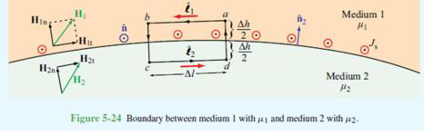
Figure 5-24 Boundary between medium 1 with μ1 and medium 2 with μ2.
Expert Solution & Answer
Want to see the full answer?
Check out a sample textbook solution
Students have asked these similar questions
Choose the appropriate answer
1) Maximum dimension of antenna is 0.5m and operating frequency is 9 GHz, thus the radius of
reactive near field region is
0.562m
1.265m
2.526m
3.265m
2) If distance between transmitter and receiver is 2km and the signal carrier frequency is
300kHz
Rapidly time-varying fields DC field Quasi-static field None
3) The polarization mismatch factor for horizontal polarization wave incident on +z axis is
is if the antenna polarization is circular
0.5
зав
0.707
1
4) Ez 0 and Hz #0 (HE modes): This is the case when neither E nor H field is transverse to the
direction of wave propagation. They are sometimes referred to as
TEM
hybrid modes
TM
TE
5) The normalized radiation intensity of an antenna is represented by:
U(6)=cos²(0) cos2 (30), w/s Half-power beamwidth HPBW is......
28.75
10
0
14.3
Choose the best answer of the following:
1- quasi-static electromagnetic field is the
a) low frequency b)high frequency c) time independent d) none of the above
2- Displacement current is taken to be negligible (compared to the conduction current) if
a) σ>>wε b)σ << wɛ c) σ =0 d) (a and c)
3- The transmission line act as inductor when it terminated by:
a) Open circuit load b) short circuit load c)matched load d)none of the above
4- The scattering aperture equals to the effective aperture when the antenna is:
a) Complex conjugate matching b) short circuit c) open circuit d) none of the above
5- The isotropic point source has directivity of:
a) Infinity b)1 c) 0 d)1.5
I selected a DC-DC converter capable of delivering 120 VDC from a 600 VDC input. When I reached out to the manufacturer, they asked for the total power consumption the converter would need to handle.To estimate this, I calculated the power requirements for the components that will use the 120 VDC supply: interior lighting, end lights, and buzzers. The breakdown is as follows:- Light Bulbs: 16 bulbs at 10 W each = 160 W- Buzzers: 2 buzzers at 5 W each = 10 W- End Lights: 2 lights at 15 W each = 30 W
This results in a total estimated power demand of 200 W.My concern is whether I should request a higher wattage rating for the converter to provide sufficient tolerance and ensure the system operates efficiently without risking an overload.
Note: The DC power system is designed specifically for a trolley
Chapter 5 Solutions
Fundamentals of Applied Electromagnetics (7th Edition)
Ch. 5.1 - What are the major differences between the...Ch. 5.1 - Prob. 2CQCh. 5.1 - How is the direction of the magnetic moment of a...Ch. 5.1 - If one of two wires of equal length is formed into...Ch. 5.1 - An electron moving in the positive x direction...Ch. 5.1 - A proton moving with a speed of 2 106 m/s through...Ch. 5.1 - A charged particle with velocity u is moving in a...Ch. 5.1 - A horizontal wire with a mass per unit length of...Ch. 5.1 - A square coil of 100 turns and 0.5 m long sides is...Ch. 5.2 - Two infinitely long parallel wires carry currents...
Ch. 5.2 - Devise a right-hand rule for the direction of the...Ch. 5.2 - What is a magnetic dipole? Describe its magnetic...Ch. 5.2 - Prob. 6ECh. 5.2 - A wire carrying a current of 4 A is formed into a...Ch. 5.2 - Prob. 8ECh. 5.3 - What are the fundamental differences between...Ch. 5.3 - Prob. 9CQCh. 5.3 - Compare the utility of applying the BiotSavart law...Ch. 5.3 - Prob. 11CQCh. 5.3 - A current I flows in the inner conductor of a long...Ch. 5.3 - The metal niobium becomes a superconductor with...Ch. 5.5 - What are the three types of magnetic materials and...Ch. 5.5 - What causes magnetic hysteresis in ferromagnetic...Ch. 5.5 - Prob. 14CQCh. 5.5 - The magnetic vector M is the vector sum of the...Ch. 5.6 - With reference to Fig. 5-24, determine the single...Ch. 5.7 - Prob. 15CQCh. 5.7 - What is the difference between self-inductance and...Ch. 5.7 - Prob. 17CQCh. 5.7 - Use Eq. (5.89) to obtain an expression for B at a...Ch. 5 - An electron with a speed of 8 106 m/s is...Ch. 5 - When a particle with charge q and mass m is...Ch. 5 - The circuit shown in Fig. P5.3 uses two identical...Ch. 5 - The rectangular loop shown in Fig. P5.4 consists...Ch. 5 - In a cylindrical coordinate system, a 2 m long...Ch. 5 - Prob. 6PCh. 5 - Prob. 7PCh. 5 - Prob. 8PCh. 5 - The loop shown in Fig. P5.9 consists of radial...Ch. 5 - An infinitely long, thin conducting sheet defined...Ch. 5 - An infinitely long wire carrying a 25 A current in...Ch. 5 - Prob. 12PCh. 5 - Prob. 13PCh. 5 - Prob. 14PCh. 5 - A circular loop of radius a carrying current I1 is...Ch. 5 - Prob. 16PCh. 5 - Prob. 17PCh. 5 - Prob. 18PCh. 5 - Three long, parallel wires are arranged as shown...Ch. 5 - A square loop placed as shown in Fig. P5.20 has 2...Ch. 5 - Prob. 21PCh. 5 - Prob. 22PCh. 5 - Repeat Problem 5.22 for a current density J=zJ0er.Ch. 5 - In a certain conducting region, the magnetic field...Ch. 5 - Prob. 25PCh. 5 - Prob. 26PCh. 5 - Prob. 27PCh. 5 - A uniform current density given by J=zj0 (A/m2)...Ch. 5 - A thin current element extending between z = L/2...Ch. 5 - In the model of the hydrogen atom proposed by Bohr...Ch. 5 - Iron contains 8.5 1028 atoms/m3. At saturation,...Ch. 5 - The xy plane separates two magnetic media with...Ch. 5 - Given that a current sheet with surface current...Ch. 5 - In Fig. P5.34, the plane defined by x y = 1...Ch. 5 - The plane boundary defined by z = 0 separates air...Ch. 5 - Prob. 36PCh. 5 - Prob. 37PCh. 5 - A solenoid with a length of 20 cm and a radius of...Ch. 5 - Prob. 39PCh. 5 - The rectangular loop shown in Fig. P5.40 is...Ch. 5 - Determine the mutual inductance between the...
Knowledge Booster


Learn more about
Need a deep-dive on the concept behind this application? Look no further. Learn more about this topic, electrical-engineering and related others by exploring similar questions and additional content below.Similar questions
- Choose the best answer 1. The minimum value of the directivity of an antenna is.......... a) Unity b) Zero 2. Very low signal strength in antenna. a) Minor lobes b) Null c) Infinite d) None c) Antenna patterns d) Major lobes 3. the maximum directivity of an antenna that normalized far field pattern is given by? 0≤0≤ and 0 ≤≤π/2,3л/2≤ p ≤ 2π E(0, 4) = {(sin 0 ((sin cos² ) 1/2 0 is a) 7.07dB b) 7.7dB elsewhere c) 8.7dB d) 9dB 4. the depth of penetration of 1 MHz wave in sea water which has conductivity mhos/meter and permeability approximately equal to that of free space is a) 25mm b) 25cm c)25m 5. The free space media can be considered as _ a) Lossy media b) lossless media c) good conductor 6. The input impedance is equal to the load impedance when a) l = 2 b)1=22 c)=4 d) 25km d) a and c .... d) a and barrow_forwardQ.1. choose the appropriate answer 1- When neither E nor H field is transverse to the direction of wave propagation. They are sometimes referred to as ...... a) hybrid mode b) TM mode c) TME modes d) TEM mode 2- If PLF-0 dB means......... a) Power is lost 100% b) Power is lost 0% c) Power is lost 50% d) none of the above 3. The half wave dipole is widely used in more applications compared to other linear antenna lengths, that is because..... a) It has high gain b) its easy matching to coaxial 75 Ohm cable c) low loss d) it has small size 4- The mode distribution for the end view waveguide shown below is a) TM12 b) TM21 c) TE20 end view d) TE02 5. When circular right hand polarized wave incident upon a horizontally polarized wave the PLF is a) 0 b)1 c)0.5 d)0.707arrow_forwarda- Single phase transmission line as in the figure below with the radius of the conductor is 0.5 cm, find the inductance of the total system. 4m 4m ao A B ob od 3m 6marrow_forward
- Please don't use ai to answer I will report you answerarrow_forwardA 3-phase, 4-wire distributor supplies a balanced voltage of 400/230 V to a load consisting of 8 A at p.f. 0-7 lagging for R-phase, 10 A at p.f. 0-8 leading for Y phase and 12 A at unity p.f. for B phase. The resistance of each line conductor is 0.4 2. The reactance of neutral is 0.2 2. Calculate the neutral current, the supply voltage for R phase and draw the phasor diagram. The phase sequence is RYB. IN ER VR Refarrow_forwardA 3-phase, 4-wire distributor supplies a balanced voltage of 400/230 V to a load consisting of 50 A at p.f. 0-866 lagging for R-phase, 30 A at p.f. 0-866 leading for Y phase and 30 A at unity pf. for B phase. The resistance of each line conductor is 0-2 Q. The area of X-section of neutral is half of any line conductor: Calculate the supply end voltage for R phase. The phase sequence is RYB.arrow_forward
- - A 3-phase, 4-wire distributor supplies a balanced voltage of 400/230 V to a load consisting of 8 A at p.f. 0.7 lagging for R-phase, 10 A at p.f. 0-8 leading for Y phase and 12 A at unity p.f. for B phase. The resistance of each line conductor is 0.4 2. The reactance of neutral is 0.2 2. Calculate the neutral current, the supply voltage for R phase and draw the phasor diagram. The phase sequence is RYB.arrow_forwardNo AI WILL REJECTarrow_forwardhelp on this one?arrow_forward
arrow_back_ios
SEE MORE QUESTIONS
arrow_forward_ios
Recommended textbooks for you
 Delmar's Standard Textbook Of ElectricityElectrical EngineeringISBN:9781337900348Author:Stephen L. HermanPublisher:Cengage Learning
Delmar's Standard Textbook Of Electricity
Electrical Engineering
ISBN:9781337900348
Author:Stephen L. Herman
Publisher:Cengage Learning
Capacitors Explained - The basics how capacitors work working principle; Author: The Engineering Mindset;https://www.youtube.com/watch?v=X4EUwTwZ110;License: Standard YouTube License, CC-BY