
Understanding Motor Controls
4th Edition
ISBN: 9781337798686
Author: Stephen L. Herman
Publisher: Delmar Cengage Learning
expand_more
expand_more
format_list_bulleted
Videos
Question
Chapter 52, Problem 1RQ
To determine
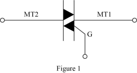
The schematic symbol for a triac.
Expert Solution & Answer
Explanation of Solution
A triac is a PNPN junction which is connected in parallel to an NPNP junction. Triac operates in the same manner as that of connection of two SCRs.
The schematic symbol for a triac is shown in Figure below.
Want to see more full solutions like this?
Subscribe now to access step-by-step solutions to millions of textbook problems written by subject matter experts!
Students have asked these similar questions
CORRECT AND DETAILED HANDWRITTEN SOLUTION WITH FBD ONLY. I WILL UPVOTE THANK YOU. CORRECT ANSWER IS ALREADY PROVIDED.
12: A steel cantilever beam 16 ft 8 in in length is subjected to a concentrated load of 320 lb acting at the freeend of the bar. A commercially available rolled steel section, designated as W12x32, is used for the beam. Assume that the total depth of the beam is 12 in, and the neutral axis of the section is in the middle. Determine the maximum tensile and compressive stresses. (Properties of commercially available rolled steel section provided in the table. Z = section modulus). ANS: σT = σC = 1,572.482 lb/in2
CORRECT AND DETAILED HANDWRITTEN SOLUTION WITH FBD ONLY. I WILL UPVOTE THANK YOU. CORRECT ANSWER IS ALREADY PROVIDED.
14: Two ½-in x 8-in cover plates are welded to two channels 10 in high to formthe cross section of the beam shown in Fig. 8-59. Loads are in a vertical plane and bendingtakes place about a horizontal axis. The moment of inertia of each channel about ahorizontal axis through the centroid is 78.5 in4. If the maximum allowable elastic bendingstress is 18,000 lb/in2, determine the maximum bending moment that may be developedin the beam.ANS: 1,236,000 lb-in.
CORRECT AND DETAILED HANDWRITTEN SOLUTION WITH FBD ONLY. I WILL UPVOTE THANK YOU. CORRECT ANSWER IS ALREADY PROVIDED.
11: A beam of circular cross section is 7 in in diameter. It is simply supported at each end and loaded by twoconcentrated loads of 20,000 lb each, applied 12 in from the ends of the beam. Determine the maximum bending stressin the beam. ANS: σ = 7,127.172 lb/in2
Knowledge Booster


Learn more about
Need a deep-dive on the concept behind this application? Look no further. Learn more about this topic, mechanical-engineering and related others by exploring similar questions and additional content below.Similar questions
- using the theorem of three moments, find all the reactions and supportsarrow_forward(An ellipsoidal trapping region for the Lorenz equations) Show that there is a certain ellipsoidal region E of the form rx2 + σy2 + σ(z − 2r)2 ≤ C such that all trajectories of the Lorenz equations eventually enter E and stay in there forever. For a much stiffer challenge, try to obtain the smallest possible value of C with this property.arrow_forwardA) In a factory, an s-type pitot tube was used to calculate the velocity of dry air for a point inside a stack. Calculate the velocity at that point (ft/sec) using following conditions: ● • • Pressure = 30.23 ± 0.01 in Hg (ambient) Pitot tube coefficient = 0.847 ± 0.03 Temperature = 122 ± 0.1 F (stack) Temperature = 71.2 ± 0.1 F (ambient) AP = 0.324 ± 0.008 in H2O (pitot tube) • AP = 0.891 ± 0.002 in H2O (stack) B) Find the dominant error(s) when determining precision for the problem. C) For part A, what is the precision in ft/sec for the velocity?arrow_forward
- Q1/ For what value of x do the power series converge: 8 (-1)n-1. x2n-1 2n-1 x3 x5 = X n=1 3 Q2/ Find the Interval of convergence and Radius of convergence of the series: 8 n Σ 3+1 n=1 (x)"arrow_forwardExample-1: l D A uniform rotor of length 0.6 m and diameter 0.4 m is made of steel (density 7810 kg/m³) is supported by identical short bearings of stiffness 1 MN/m in the horizontal and vertical directions. If the distance between the bearings is 0.7 m, determine the natural frequencies and plot whirl speed map. Solution: Barrow_forwardfind the laplace transform for the flowing function 2(1-e) Ans. F(s)=- S 12) k 0 Ans. F(s)= k s(1+e) 0 a 2a 3a 4a 13) 2+ Ans. F(s)= 1 s(1+e") 3 14) f(t)=1, 0arrow_forwardFind the solution of the following Differential Equations Using Laplace Transforms 1) 4y+2y=0. y(0)=2. y'(0)=0. 2) y+w²y=0, (0)=A, y'(0)=B. 3) +2y-8y 0. y(0)=1. y'(0)-8. 4)-2-3y=0, y(0)=1. y'(0)=7. 5) y-ky'=0, y(0)=2, y'(0)=k. 6) y+ky'-2k²y=0, y(0)=2, y'(0) = 2k. 7) '+4y=0, y(0)=2.8 8) y+y=17 sin(21), y(0)=-1. 9) y-y-6y=0, y(0)=6, y'(0)=13. 10) y=0. y(0)=4, y' (0)=0. 11) -4y+4y-0, y(0)=2.1. y'(0)=3.9 12) y+2y'+2y=0, y(0)=1, y'(0)=-3. 13) +7y+12y=21e". y(0)=3.5. y'(0)=-10. 14) "+9y=10e". y(0)=0, y'(0)=0. 15) +3y+2.25y=91' +64. y(0)=1. y'(0) = 31.5 16) -6y+5y-29 cos(2t). y(0)=3.2, y'(0)=6.2 17) y+2y+2y=0, y(0)=0. y'(0)=1. 18) y+2y+17y=0, y(0)=0. y'(0)=12. 19) y"-4y+5y=0, y(0)=1, y'(0)=2. 20) 9y-6y+y=0, (0)-3, y'(0)=1. 21) -2y+10y=0, y(0)=3, y'(0)=3. 22) 4y-4y+37y=0, y(0)=3. y'(0)=1.5 23) 4y-8y+5y=0, y(0)=0, y'(0)=1. 24) ++1.25y-0, y(0)=1, y'(0)=-0.5 25) y 2 cos(r). y(0)=2. y'(0) = 0. 26) -4y+3y-0, y(0)=3, y(0) 7. 27) y+2y+y=e y(0)=0. y'(0)=0. 28) y+2y-3y=10sinh(27), y(0)=0. y'(0)=4. 29)…arrow_forwardAuto Controls A union feedback control system has the following open loop transfer function where k>0 is a variable proportional gain i. for K = 1 , derive the exact magnitude and phase expressions of G(jw). ii) for K = 1 , identify the gaincross-over frequency (Wgc) [where IG(jo))| 1] and phase cross-overfrequency [where <G(jw) = - 180]. You can use MATLAB command "margin" to obtain there quantities. iii) Calculate gain margin (in dB) and phase margin (in degrees) ·State whether the closed-loop is stable for K = 1 and briefly justify your answer based on the margin . (Gain marginPhase margin) iv. what happens to the gain margin and Phase margin when you increase the value of K?you You can use for loop in MATLAB to check that.Helpful matlab commands : if, bode, margin, rlocus NO COPIED SOLUTIONSarrow_forwardThe 120 kg wheel has a radius of gyration of 0.7 m. A force P with a magnitude of 50 N is applied at the edge of the wheel as seen in the diagram. The coefficient of static friction is 0.3, and the coefficient of kinetic friction is 0.25. Find the acceleration and angular acceleration of the wheel.arrow_forwardAuto Controls Using MATLAB , find the magnitude and phase plot of the compensators NO COPIED SOLUTIONSarrow_forward4-81 The corner shown in Figure P4-81 is initially uniform at 300°C and then suddenly exposed to a convection environment at 50°C with h 60 W/m². °C. Assume the = 2 solid has the properties of fireclay brick. Examine nodes 1, 2, 3, 4, and 5 and deter- mine the maximum time increment which may be used for a transient numerical calculation. Figure P4-81 1 2 3 4 1 cm 5 6 1 cm 2 cm h, T + 2 cmarrow_forwardAuto Controls A union feedback control system has the following open loop transfer function where k>0 is a variable proportional gain i. for K = 1 , derive the exact magnitude and phase expressions of G(jw). ii) for K = 1 , identify the gaincross-over frequency (Wgc) [where IG(jo))| 1] and phase cross-overfrequency [where <G(jw) = - 180]. You can use MATLAB command "margin" to obtain there quantities. iii) Calculate gain margin (in dB) and phase margin (in degrees) ·State whether the closed-loop is stable for K = 1 and briefly justify your answer based on the margin . (Gain marginPhase margin) iv. what happens to the gain margin and Phase margin when you increase the value of K?you You can use for loop in MATLAB to check that.Helpful matlab commands : if, bode, margin, rlocus NO COPIED SOLUTIONSarrow_forwardarrow_back_iosSEE MORE QUESTIONSarrow_forward_ios
Recommended textbooks for you
 Understanding Motor ControlsMechanical EngineeringISBN:9781337798686Author:Stephen L. HermanPublisher:Delmar Cengage Learning
 Precision Machining Technology (MindTap Course Li...Mechanical EngineeringISBN:9781285444543Author:Peter J. Hoffman, Eric S. Hopewell, Brian JanesPublisher:Cengage Learning
Understanding Motor Controls
Mechanical Engineering
ISBN:9781337798686
Author:Stephen L. Herman
Publisher:Delmar Cengage Learning
Precision Machining Technology (MindTap Course Li...
Mechanical Engineering
ISBN:9781285444543
Author:Peter J. Hoffman, Eric S. Hopewell, Brian Janes
Publisher:Cengage Learning
Material Science, Phase Diagrams, Part 1; Author: Welt der Werkstoffe;https://www.youtube.com/watch?v=G83ZaoB3XCc;License: Standard Youtube License