
VECTOR MECHANICS FOR ENGINEERS: STATICS
12th Edition
ISBN: 9781260536225
Author: BEER
Publisher: MCG
expand_more
expand_more
format_list_bulleted
Concept explainers
Videos
Textbook Question
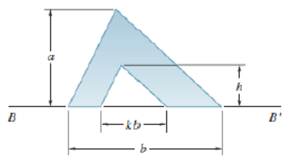
Chapter 5.1, Problem 5.33P
Knowing that the distance h has been selected to maximize the distance
Expert Solution & Answer
Want to see the full answer?
Check out a sample textbook solution
Students have asked these similar questions
Please do not use any AI tools to solve this question.
I need a fully manual, step-by-step solution with clear explanations, as if it were done by a human tutor.
No AI-generated responses, please.
Please do not use any AI tools to solve this question.
I need a fully manual, step-by-step solution with clear explanations, as if it were done by a human tutor.
No AI-generated responses, please.
Please do not use any AI tools to solve this question.
I need a fully manual, step-by-step solution with clear explanations, as if it were done by a human tutor.
No AI-generated responses, please.
Chapter 5 Solutions
VECTOR MECHANICS FOR ENGINEERS: STATICS
Ch. 5.1 - 5.1 through 5.9 Locate the centroid of the plane...Ch. 5.1 - Locate the centroid of the plane area shown.Ch. 5.1 - Locate the centroid of the plane area shown.Ch. 5.1 - Locate the centroid of the plane area shown.Ch. 5.1 - Locate the centroid of the plane area shown.Ch. 5.1 - Locate the centroid of the plane area shown.Ch. 5.1 - Locate the centroid of the plane area shown.Ch. 5.1 - Locate the centroid of the plane area shown.Ch. 5.1 - Locate the centroid of the plane area shown.Ch. 5.1 - Locate the centroid of the plane area shown.
Ch. 5.1 - Locate the centroid of the plane area shown.Ch. 5.1 - Locate the centroid of the plane area shown.Ch. 5.1 - Locate the centroid of the plane area shown.Ch. 5.1 - Locate the centroid of the plane area shown.Ch. 5.1 - Locate the centroid of the plane area shown.Ch. 5.1 - PROBLEM 5.16 Determine the y coordinate of the...Ch. 5.1 - Show that as r1 approaches r2, the location of the...Ch. 5.1 - For the area shown, determine the ratio a/b for...Ch. 5.1 - For the semiannular area of Prob. 5.12, determine...Ch. 5.1 - A built-up beam is constructed by nailing seven...Ch. 5.1 - The horizontal x axis is drawn through the...Ch. 5.1 - The horizontal x-axis is drawn through the...Ch. 5.1 - PROBLEM 5.23 The first moment of the shaded area...Ch. 5.1 - A thin, homogeneous wire is bent to form the...Ch. 5.1 - A thin, homogeneous wire is bent to form the...Ch. 5.1 - A thin, homogeneous wire is bent to form the...Ch. 5.1 - A thin, homogeneous wire is bent to form the...Ch. 5.1 - The homogeneous wire ABC is bent into a...Ch. 5.1 - The frame for a sign is fabricated from thin, flat...Ch. 5.1 - The homogeneous wire ABCD is bent as shown and is...Ch. 5.1 - The homogeneous wire ABCD is bent as shown and is...Ch. 5.1 - Determine the distance h for which the centroid of...Ch. 5.1 - Knowing that the distance h has been selected to...Ch. 5.2 - Determine by direct integration the centroid of...Ch. 5.2 - 5.34 through 5.36 Determine by direct integration...Ch. 5.2 - 5.34 through 5.36 Determine by direct integration...Ch. 5.2 - 5.37 through 5.39 Determine by direct integration...Ch. 5.2 - 5.37 through 5.39 Determine by direct integration...Ch. 5.2 - 5.37 through 5.39 Determine by direct integration...Ch. 5.2 - 5.40 and 5.41 Determine by direct integration the...Ch. 5.2 - 5.40 and 5.41 Determine by direct integration the...Ch. 5.2 - Determine by direct integration the centroid of...Ch. 5.2 - 5.43 and 5.44 Determine by direct integration the...Ch. 5.2 - 5.43 and 5.44 Determine by direct integration the...Ch. 5.2 - 5.45 and 5.46 A homogeneous wire is bent into the...Ch. 5.2 - 5.45 and 5.46 A homogeneous wire is bent into the...Ch. 5.2 - A homogeneous wire is bent into the shape shown....Ch. 5.2 - 5.48 and 5.49 Determine by direct integration the...Ch. 5.2 - 5.48 and 5.49 Determine by direct integration the...Ch. 5.2 - Determine the centroid of the area shown in terms...Ch. 5.2 - Determine the centroid of the area shown when a =...Ch. 5.2 - Determine the volume and the surface area of the...Ch. 5.2 - Determine the volume and the surface area of the...Ch. 5.2 - Determine the volume and the surface area of the...Ch. 5.2 - Determine the volume and the surface area of the...Ch. 5.2 - Determine the volume of the solid generated by...Ch. 5.2 - Verify that the expressions for the volumes of the...Ch. 5.2 - Knowing that two equal caps have been removed from...Ch. 5.2 - Three different drive belt profiles are to be...Ch. 5.2 - Determine the capacity, in liters, of the punch...Ch. 5.2 - Determine the volume and total surface area of the...Ch. 5.2 - Determine the volume and weight of the solid brass...Ch. 5.2 - Determine the total surface area of the solid...Ch. 5.2 - Determine the volume of the brass collar obtained...Ch. 5.2 - The shade for a wall-mounted light is formed from...Ch. 5.3 - 5.66 and 5.67 For the beam and loading shown,...Ch. 5.3 - 5.66 and 5.67 For the beam and loading shown,...Ch. 5.3 - 5.68 through 5.73 Determine the reactions at the...Ch. 5.3 - 5.68 through Determine the reactions at the beam...Ch. 5.3 - 5.68 through 5.73 Determine the reactions at the...Ch. 5.3 - 5.68 through Determine the reactions at the beam...Ch. 5.3 - 5.68 through 5.73 Determine the reactions at the...Ch. 5.3 - 5.68 through 5.73 Determine the reactions at the...Ch. 5.3 - Determine (a) the distance a so that the vertical...Ch. 5.3 - Determine (a) the distance a so that the reaction...Ch. 5.3 - Determine the reactions at the beam supports for...Ch. 5.3 - Determine (a) the distributed load w0 at the end D...Ch. 5.3 - The beam AB supports two concentrated loads and...Ch. 5.3 - For the beam and loading of Prob. 5.78, determine...Ch. 5.3 - The cross section of a concrete dam is as shown....Ch. 5.3 - The cross section of a concrete dam is as shown....Ch. 5.3 - The dam for a lake is designed to withstand the...Ch. 5.3 - The base of a dam for a lake is designed to resist...Ch. 5.3 - Prob. 5.84PCh. 5.3 - Prob. 5.85PCh. 5.3 - The 3 4-m side AB of a tank is hinged at its...Ch. 5.3 - The 3 4-m side of an open tank is hinged at its...Ch. 5.3 - A 0.5 0.8-m gate AB is located at the bottom of a...Ch. 5.3 - A 0.5 0.8-m gate AB is located at the bottom of a...Ch. 5.3 - A 4 2-ft gate is hinged at A and is held in...Ch. 5.3 - Fig. P5.90 5.91 Solve Prob. 5.90 if the gate...Ch. 5.3 - A prismatically shaped gate placed at the end of a...Ch. 5.3 - A prismatically shaped gate placed at the end of a...Ch. 5.3 - A long trough is supported by a continuous hinge...Ch. 5.3 - The square gate AB is held in the position shown...Ch. 5.4 - Consider the composite body shown. Determine (a)...Ch. 5.4 - A cone and a cylinder of the same radius a and...Ch. 5.4 - Determine the location of the center of gravity of...Ch. 5.4 - Prob. 5.99PCh. 5.4 - For the stop bracket shown, locate the x...Ch. 5.4 - Fig. P5.100 and P5.101 5.101 For the stop bracket...Ch. 5.4 - Prob. 5.102PCh. 5.4 - Prob. 5.103PCh. 5.4 - For the machine element shown, locate the y...Ch. 5.4 - For the machine element shown, locate the x...Ch. 5.4 - 5.106 and 5.107 Locate the center of gravity of...Ch. 5.4 - 5.106 and 5.107 Locate the center of gravity of...Ch. 5.4 - A corner reflector for tracking by radar has two...Ch. 5.4 - A wastebasket, designed to fit in the corner of a...Ch. 5.4 - An elbow for the duct of a ventilating system is...Ch. 5.4 - A window awning is fabricated from sheet metal...Ch. 5.4 - Locate the center of gravity of the sheet-metal...Ch. 5.4 - Locate the center of gravity of the sheet-metal...Ch. 5.4 - A thin steel wire with a uniform cross section is...Ch. 5.4 - The frame of a greenhouse is constructed from...Ch. 5.4 - Locate the center of gravity of the figure shown,...Ch. 5.4 - Prob. 5.117PCh. 5.4 - A scratch awl has a plastic handle and a steel...Ch. 5.4 - PROBLEM 5.117 A bronze bushing is mounted inside a...Ch. 5.4 - PROBLEM 5.120 A brass collar, of length 2.5 in.,...Ch. 5.4 - PROBLEM 5.121 The three legs of a small...Ch. 5.4 - Prob. 5.122PCh. 5.4 - Determine by direct integration the values of x...Ch. 5.4 - Prob. 5.124PCh. 5.4 - PROBLEM 5.125 Locate the centroid of the volume...Ch. 5.4 - Prob. 5.126PCh. 5.4 - Prob. 5.127PCh. 5.4 - PROBLEM 5.128 Locate the centroid of the volume...Ch. 5.4 - PROBLEM 5.129 Locate the centroid of the volume...Ch. 5.4 - Show that for a regular pyramid of height h and n...Ch. 5.4 - PROBLEM 5.131 Determine by direct integration the...Ch. 5.4 - PROBLEM 5.132 The sides and the base of a punch...Ch. 5.4 - Locate the centroid of the section shown, which...Ch. 5.4 - Locate the centroid of the section shown, which...Ch. 5.4 - Determine by direct integration the location of...Ch. 5.4 - Alter grading a lot, a builder places four stakes...Ch. 5 - 5.137 and 5.138 Locate the centroid of the plane...Ch. 5 - 5.137 and 5.138 Locate the centroid of the plane...Ch. 5 - Prob. 5.139RPCh. 5 - Determine by direct integration the centroid of...Ch. 5 - Determine by direct integration the centroid of...Ch. 5 - The escutcheon (a decorative plate placed on a...Ch. 5 - Determine the reactions at the supports for the...Ch. 5 - A beam is subjected to a linearly distributed...Ch. 5 - A tank is divided into two sections by a 1 1-m...Ch. 5 - Determine the y coordinate of the centroid of the...Ch. 5 - An 8-in.-diameter cylindrical duct and a 4 8-in....Ch. 5 - Three brass plates are brazed to a steel pipe to...
Knowledge Booster


Learn more about
Need a deep-dive on the concept behind this application? Look no further. Learn more about this topic, mechanical-engineering and related others by exploring similar questions and additional content below.Similar questions
- [Q2]: The cost information supplied by the cost accountant is as follows:Sales 20,00 units, $ 10 per unitCalculate the (a/ newsale guantity and (b) new selling price to earn the sameVariable cost $ 6 per unit, Fixed Cost $ 30,000, Profit $ 50,000profit ifi) Variable cost increases by $ 2 per unitil) Fixed cost increase by $ 10,000Ili) Variable cost increase by $ 1 per unit and fixed cost reduces by $ 10,000arrow_forwardcan you please help me perform Visual Inspection and Fractography of the attatched image: Preliminary examination to identify the fracture origin, suspected fatigue striation, and corrosion evidences.arrow_forwardcan you please help[ me conduct Causal Analysis (FTA) on the scenario attatched: FTA diagram which is a fault tree analysis diagram will be used to gain an overview of the entire path of failure from root cause to the top event (i.e., the swing’s detachment) and to identify interactions between misuse, material decay and inspection errors.arrow_forward
- hi can you please help me in finding the stress intensity factor using a k-calcluator for the scenario attathced in the images.arrow_forwardHi, can you please help me .Identify and justify suitable analytical techniques of the scenario below, bearing in mind the kinds of information being handled to reach a conclusion (methodology). A child swing set was discovered to have failed at the fixing at the top of the chains connecting the seat to the top of the swing set. A 12 mm threaded steel bolt, connecting the shackle to the top beam, failed at the start of the threaded region on the linkage closest to the outside side of the swing set . The linkage and bolts were made of electro galvanised mild steel . The rigid bar chain alternatives and fixings were of the same material and appeared to be fitted in accordance with guidelines. The yield strength of the steel used is 260 MPa and the UTS is 380 MPa. The bolt that failed was threaded using a standard thread with a pitch (distance between threads) of 1.75 mm and a depth of approximately 1.1 mm. The swing set in question had been assigned to ‘toddlers’ with the application of…arrow_forwardHi, can you please define and calculate the failure mode of the linkage that failed on the swing (images added) : A child swing set was discovered to have failed at the fixing at the top of the chains connecting the seat to the top of the swing set. A 12 mm threaded steel bolt, connecting the shackle to the top beam, failed at the start of the threaded region on the linkage closest to the outside side of the swing set . The linkage and bolts were made of electro galvanised mild steel . The rigid bar chain alternatives and fixings were of the same material and appeared to be fitted in accordance with guidelines. The yield strength of the steel used is 260 MPa and the UTS is 380 MPa. The bolt that failed was threaded using a standard thread with a pitch (distance between threads) of 1.75 mm and a depth of approximately 1.1 mm. The swing set in question had been assigned to ‘toddlers’ with the application of a caged-type seat. However, the location was within the play area not…arrow_forward
- Page 11-68. The rectangular plate shown is subjected to a uniaxial stress of 2000 psi. Compute the shear stress and the tensile developed on a plane forming an angle of 30° with the longitud axis of the member. (Hint: Assume a cross-sectional area of unity) 2000 psi 2000 psi hparrow_forward11-70. A shear stress (pure shear) of 5000 psi exists on an element. (a) Determine the maximum tensile and compressive stresses caused in the element due to this shear. (b) Sketch the element showing the planes on which the maximum tensile and compressive stresses act.arrow_forward11-20. An aluminum specimen of circular cross section, 0.50 in. in diameter, ruptured under a tensile load of 12,000 lb. The plane of failure was found to be at 48° with a plane perpendicular to the longitudinal axis of the specimen. (a) Compute the shear stress on the failure plane. (b) Compute the maximum tensile stress. (c) Compute the tensile stress on the failure plane. hparrow_forward
- A long flat steel bar 13 mm thick and 120 mm wide has semicircular grooves as shown and carries a tensile load of 50 kN Determine the maximum stress if plate r= 8mm r=21mm r=38mmarrow_forwardProblem 13: F₁ = A =250 N 30% Determine the moment of each of the three forces about point B. F₂ = 300 N 60° 2 m -3 m B 4 m F3=500 Narrow_forward3 kN 3 kN 1.8 kN/m 80 mm B 300 mm D an 1.5 m-1.5 m--1.5 m- PROBLEM 5.47 Using the method of Sec. 5.2, solve Prob. 5.16 PROBLEM 5.16 For the beam and loading shown, determine the maximum normal stress due to bending on a transverse section at C.arrow_forward
arrow_back_ios
SEE MORE QUESTIONS
arrow_forward_ios
Recommended textbooks for you
 International Edition---engineering Mechanics: St...Mechanical EngineeringISBN:9781305501607Author:Andrew Pytel And Jaan KiusalaasPublisher:CENGAGE L
International Edition---engineering Mechanics: St...
Mechanical Engineering
ISBN:9781305501607
Author:Andrew Pytel And Jaan Kiusalaas
Publisher:CENGAGE L
Introduction To Engineering Drawing; Author: EzEd Channel;https://www.youtube.com/watch?v=z4xZmBpXIzQ;License: Standard youtube license