
Electrical Wiring Residential
19th Edition
ISBN: 9781337101837
Author: Ray C. Mullin, Phil Simmons
Publisher: Cengage Learning
expand_more
expand_more
format_list_bulleted
Concept explainers
Videos
Textbook Question
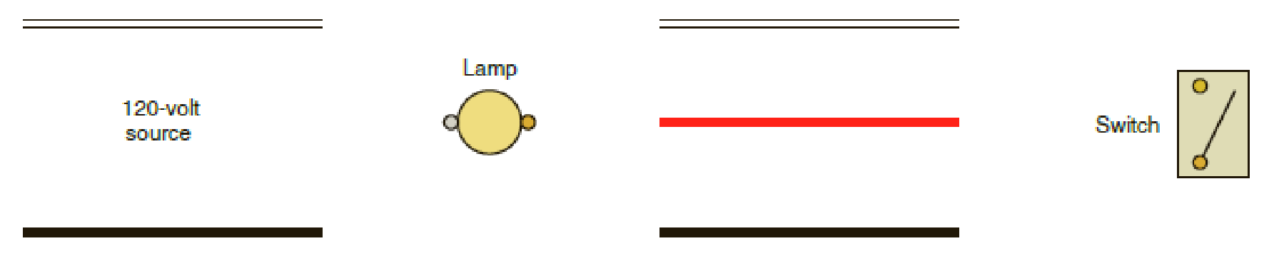
Chapter 5, Problem 9R
Complete the connections for the diagram. Installation is cable.
Expert Solution & Answer

Trending nowThis is a popular solution!

Students have asked these similar questions
Find Vo
Using Properties to find the Z-Transform including the region of convergence for
Sol
x(n): = n
n
cos(0.2(n-2))u(n - 1)
Xch]=h+1-1 (1) h+h cos(0.27 (^_1_-1))
* shift → ht
44h-13
can you complete my solution
Find Ix
Chapter 5 Solutions
Electrical Wiring Residential
Ch. 5 - The identified grounded circuit conductor must be...Ch. 5 - Explain how lighting switches are rated.Ch. 5 - Prob. 4RCh. 5 - Prob. 5RCh. 5 - To control a lighting load from one control point,...Ch. 5 - Prob. 7RCh. 5 - Complete the connections in the following...Ch. 5 - Complete the connections for the diagram....Ch. 5 - A three-way switch may be compared to a _____...Ch. 5 - Prob. 11R
Ch. 5 - Complete the connections in the following...Ch. 5 - When connecting 4-way switches, care must be taken...Ch. 5 - Show the connections for a ceiling outlet that is...Ch. 5 - Match the following switch types with the correct...Ch. 5 - When connecting single-pole, 3-way, and 4-way...Ch. 5 - What section of the Code emphasizes the fact that...Ch. 5 - If you had to install an underground 3-wire feeder...Ch. 5 - Is it always necessary to attach the bare...Ch. 5 - List the methods by which an equipment grounding...Ch. 5 - When two nonmetallic-sheathed cables (Type NM-B)...Ch. 5 - Define an equipment grounding conductor.Ch. 5 - When metal toggle switchplates are used with...Ch. 5 - Does the Code permit the ampacity of switch legs...Ch. 5 - Prob. 26RCh. 5 - Prob. 27R
Additional Engineering Textbook Solutions
Find more solutions based on key concepts
1.2 Explain the difference between geodetic and plane
surveys,
Elementary Surveying: An Introduction To Geomatics (15th Edition)
CONCEPT QUESTIONS
15.CQ3 The ball rolls without slipping on the fixed surface as shown. What is the direction ...
Vector Mechanics for Engineers: Statics and Dynamics
This optional Google account security feature sends you a message with a code that you must enter, in addition ...
SURVEY OF OPERATING SYSTEMS
Locate the centroid of the area. Prob. 9-17
INTERNATIONAL EDITION---Engineering Mechanics: Statics, 14th edition (SI unit)
The job of the _____ is to fetch instructions, carry out the operations commanded by the instructions, and prod...
Starting Out With Visual Basic (8th Edition)
Comprehension Check 7-14
The power absorbed by a resistor can be given by P = I2R, where P is power in units of...
Thinking Like an Engineer: An Active Learning Approach (4th Edition)
Knowledge Booster


Learn more about
Need a deep-dive on the concept behind this application? Look no further. Learn more about this topic, electrical-engineering and related others by exploring similar questions and additional content below.Similar questions
- J. na ul-n-1) X (n) = na^ = na^ u(-(n+1)) (1-1+4)= 741-1 4[cn+1)] +1 * Z (^- 1-1 (n-1) a て why ✓ (n) Z , ༥(-༡) ur-n) Znxcm) -Zx X (n) (n-1) a auc-n) = X(n) ぞ 2-9³arrow_forwardTurn trip logic into boolean algebra gates logic?arrow_forwardFind the Z-transform including the region of convergence for the following function 12 (¹)" [u(n) – u(n − 5)] -arrow_forward
- Find the inverse Z-traform of X(z)= z 2 +z (z-0.125)³ (z-0.25)arrow_forwardA separately excited 6-kilowatt generator has a terminal voltage of 135V at no load. At full load, the terminal voltage is 120V with speed and field excitation unchanged. Armature resistance = = 0.25 ohm. A. What is the amount of voltage decrease caused by armature reaction and the voltage regulation?arrow_forwardJ. A sampling system can be set to adjust its sampling rate in 25 He steps. Considering the signal spectra pleted below, specify the minimum sampling rate setting for the signals: a)x(1) b)(1)+(1) 985)+20 0,09 0:00 0,0 106) 100) SORO -2501 250V (1500+501) 。 1500+50V 201 2500arrow_forward
- 1. For this problem, state your answers to 4 significant figures. (1)For the message signal shown below, sketch the phase-meduced form and 4-5/N rad V. Specify values of the miniman & maximum instantaneous frequencies in He (b) Find the approximate bandwidth of the phase-modulaud signal, assuming that the effective handwidth of the message is equal to its 4th harmonic frequency (N-2015 101 2x10' 159-arrow_forward4. For the filter shown below, with an input signal whose PSD by 20 (4) Find the pet power in (b) Find the trafor (4) Find the power spel de PSD) of 4 put signat (d) Find the talutput power of the signal a C-58-18 -arrow_forward2.80+4'selevision stations are to be transmited deough a single fiber optic cable using uncompressed PCM and TDM. Each station comprises one 22 kHz audio channel samplod at (1+0.24) times the Nyquist rate and encoded at a bit dop of 12 bSa, plan one 2.0 MHz video channel sampled at the mininum rite The video signal must be transmitted with an accuracy of better than (20 3) Find De (minimum) bit depth of the video signal. b) Find the bit rate associated with a single television station, including both audio and video e) Find the minimus bandwidth (the total multiplexed PCM signal.arrow_forward
- 5. Consider a Shor who (4) Skh the impulse repom of the Chor for -5%, a-2+5. Omie weer de Sher is drain canal and explain sty odical, chronic sale of a hat will result in a coal for, and expls why itarrow_forwardFind the inverse Z-transform of X(z) using partial fraction method X(z) = z²+Z Z2-3Z+2 for i) ROC 12 iii) ROC |z| <1arrow_forward.The previous solution does not explain the steps Consider the signal: f(t) = 글씨를 1 0, otherwise Use the Fourier transform formula to find F(w).arrow_forward
arrow_back_ios
SEE MORE QUESTIONS
arrow_forward_ios
Recommended textbooks for you
 EBK ELECTRICAL WIRING RESIDENTIALElectrical EngineeringISBN:9781337516549Author:SimmonsPublisher:CENGAGE LEARNING - CONSIGNMENT
EBK ELECTRICAL WIRING RESIDENTIAL
Electrical Engineering
ISBN:9781337516549
Author:Simmons
Publisher:CENGAGE LEARNING - CONSIGNMENT
Types of House Wiring - Types of Electrical Wiring - Electrical Wiring; Author: Learning Engineering;https://www.youtube.com/watch?v=A5P-buWX-dA;License: Standard Youtube License