
Concept explainers
Plot the shear diagram, bending moment diagram, axial force diagram, and the qualitative deflected shape of the frame.
Explanation of Solution
Write the condition for static instability, determinacy and indeterminacy of plane frames as follows:
Here, number of members is m, number of external reactions is r, the number of joints is j, and the number of elastic hinges is
Find the degree of static indeterminacy (i) using the equation;
Refer to the Figure in the question;
The number of members (m) is 3.
The number of external reactions (r) is 3.
The number of joints (j) is 4.
The number of elastic hinges
Substitute the values in Equation (2);
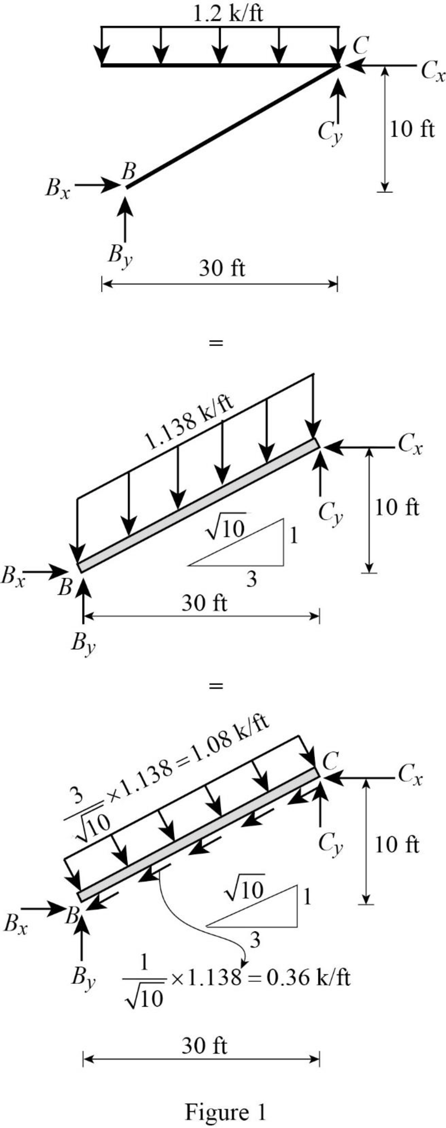
Show the equivalence of uniformly distributed load as in Figure 1.
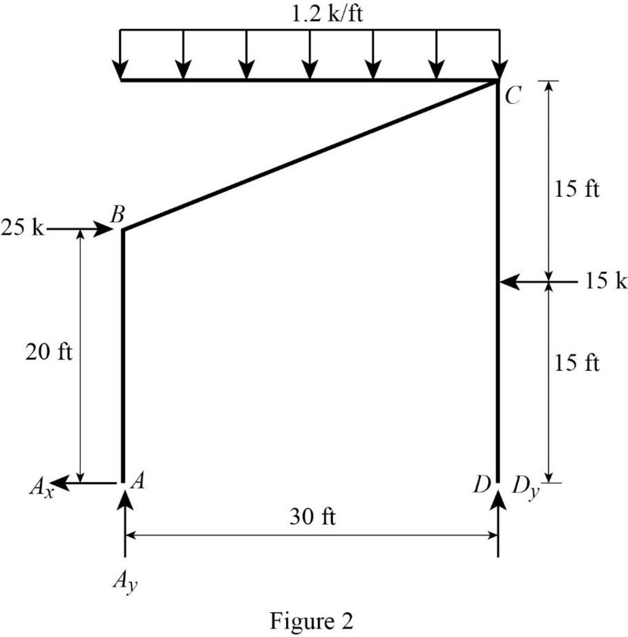
Show the free-body diagram of the entire frame as in Figure 2.
Find the horizontal reaction at point A by resolving the horizontal component of forces.
Find the vertical reaction at point D by taking moment about point A.
Find the vertical reaction at point A by resolving the vertical component of forces.
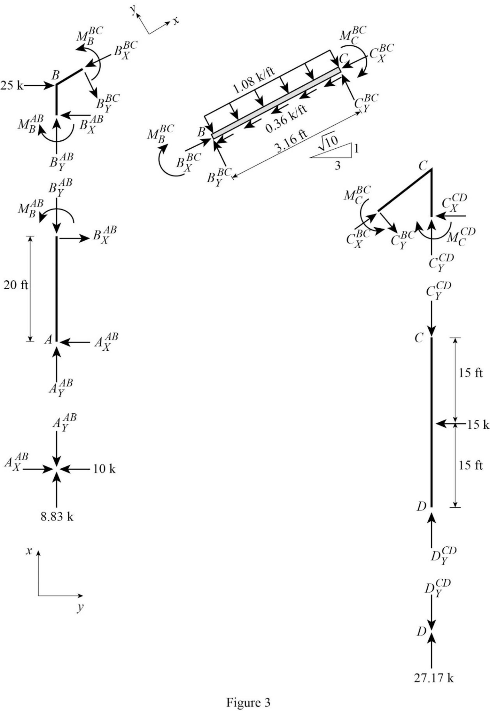
Show the free-body diagram of the members and joints of the entire frame as in Figure 3.
Consider point A:
Resolve the vertical component of forces.
Resolve the horizontal component of forces.
Consider the member AB:
Resolve the vertical component of forces.
Take moment about the point B.
Consider the point D:
Resolve the vertical component of forces.
Consider the member CD:
Resolve the vertical component of forces.
Take moment about the point C.
Resolve the horizontal component of forces.
Consider the point C:
Resolve the vertical component of forces.
Resolve the horizontal component of forces.
Take moment about the point C.
Consider the section BC:
Resolve the vertical component of forces.
Resolve the horizontal component of forces.
Take moment about point B:
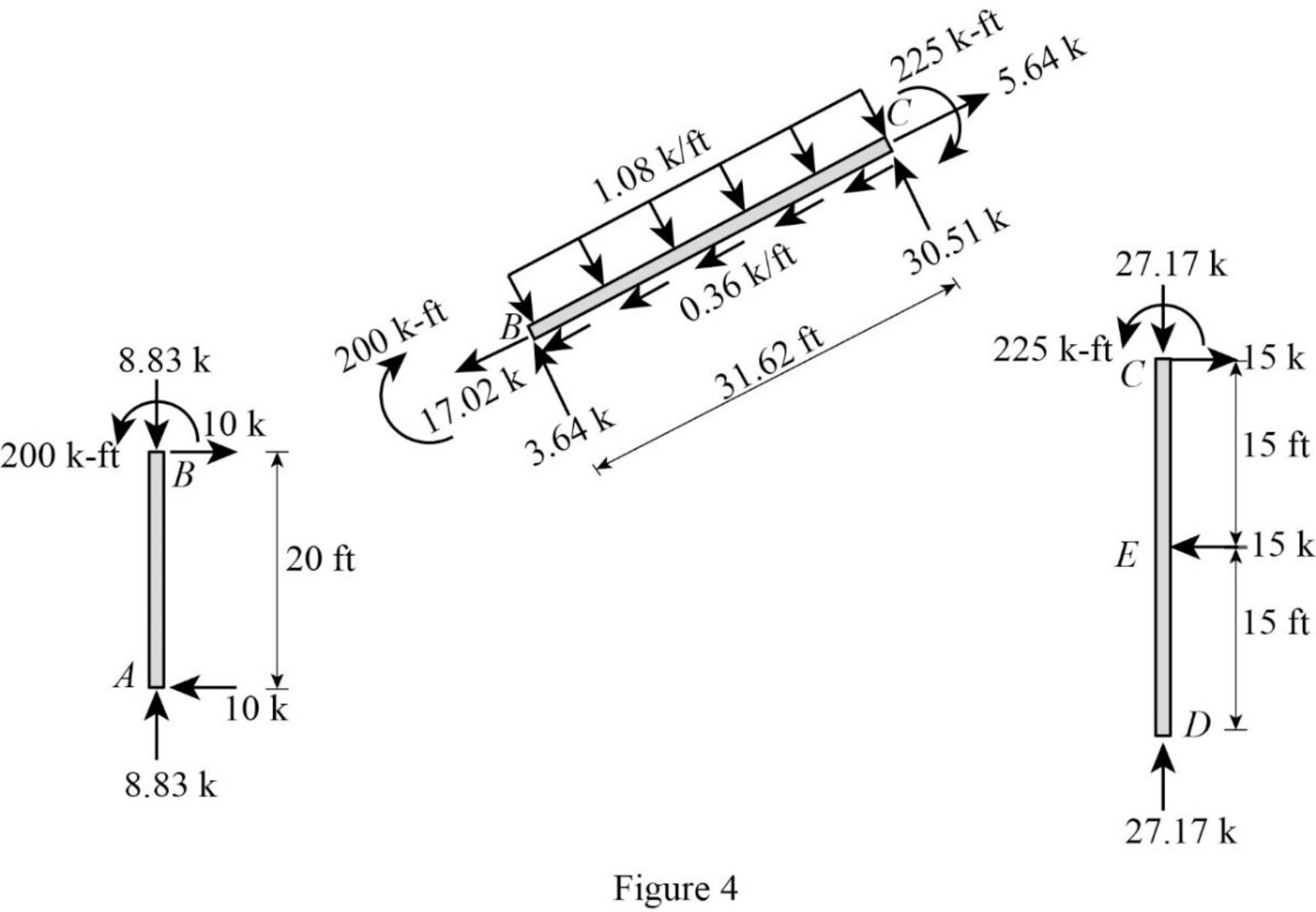
Plot the moment end forces of the frame as in Figure 4.
Refer to the moment end force diagram plot the shear diagram, bending moment diagram, and the axial force diagrams.
Plot the shear force diagram as in Figure 5.
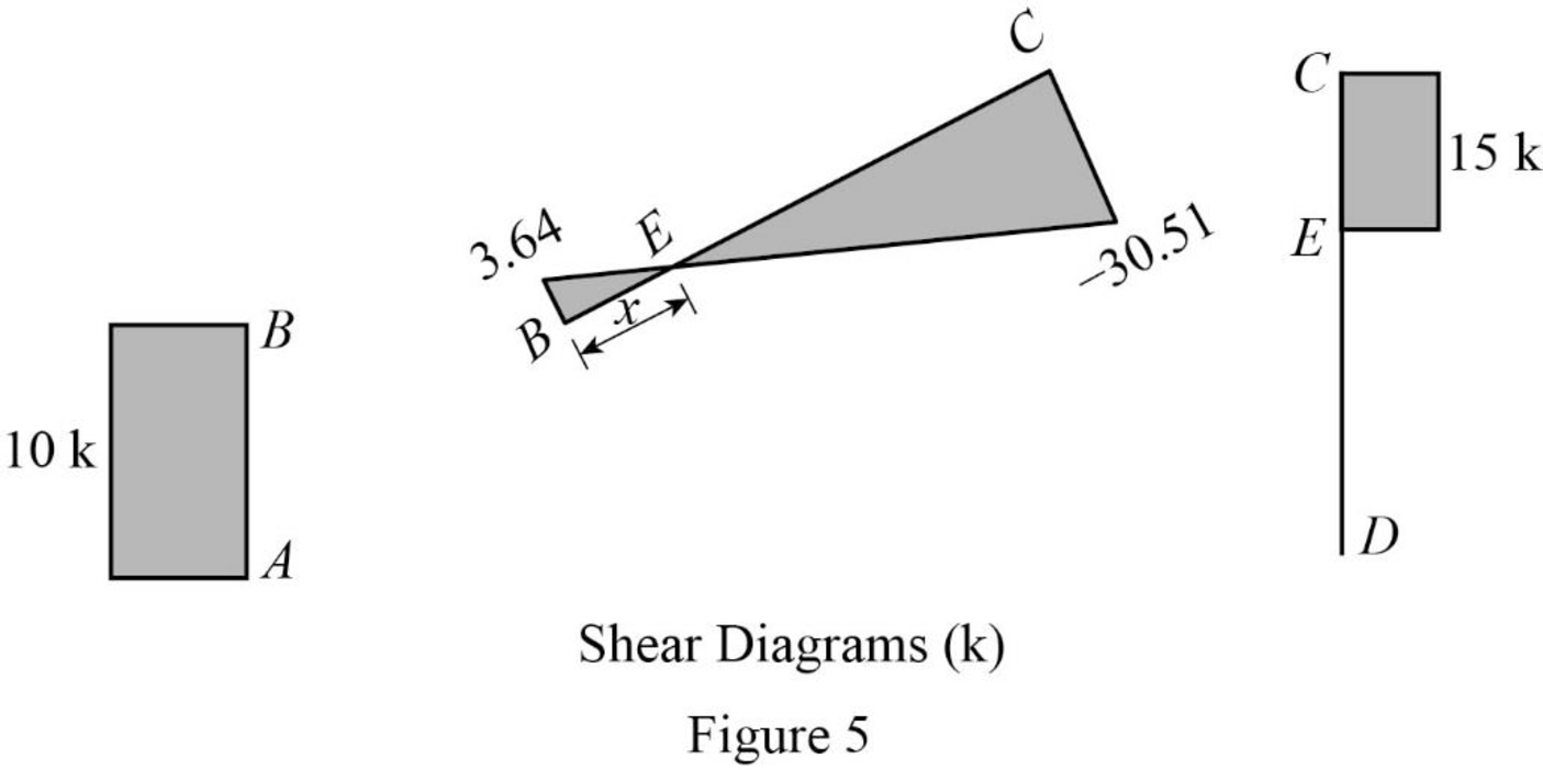
The maximum bending moment occurs where the shear force changes sign.
Consider the section BEC, use the similar triangle concept.
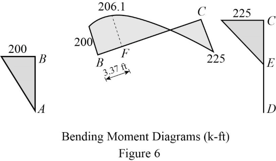
Plot the bending moment diagram as in Figure 6.
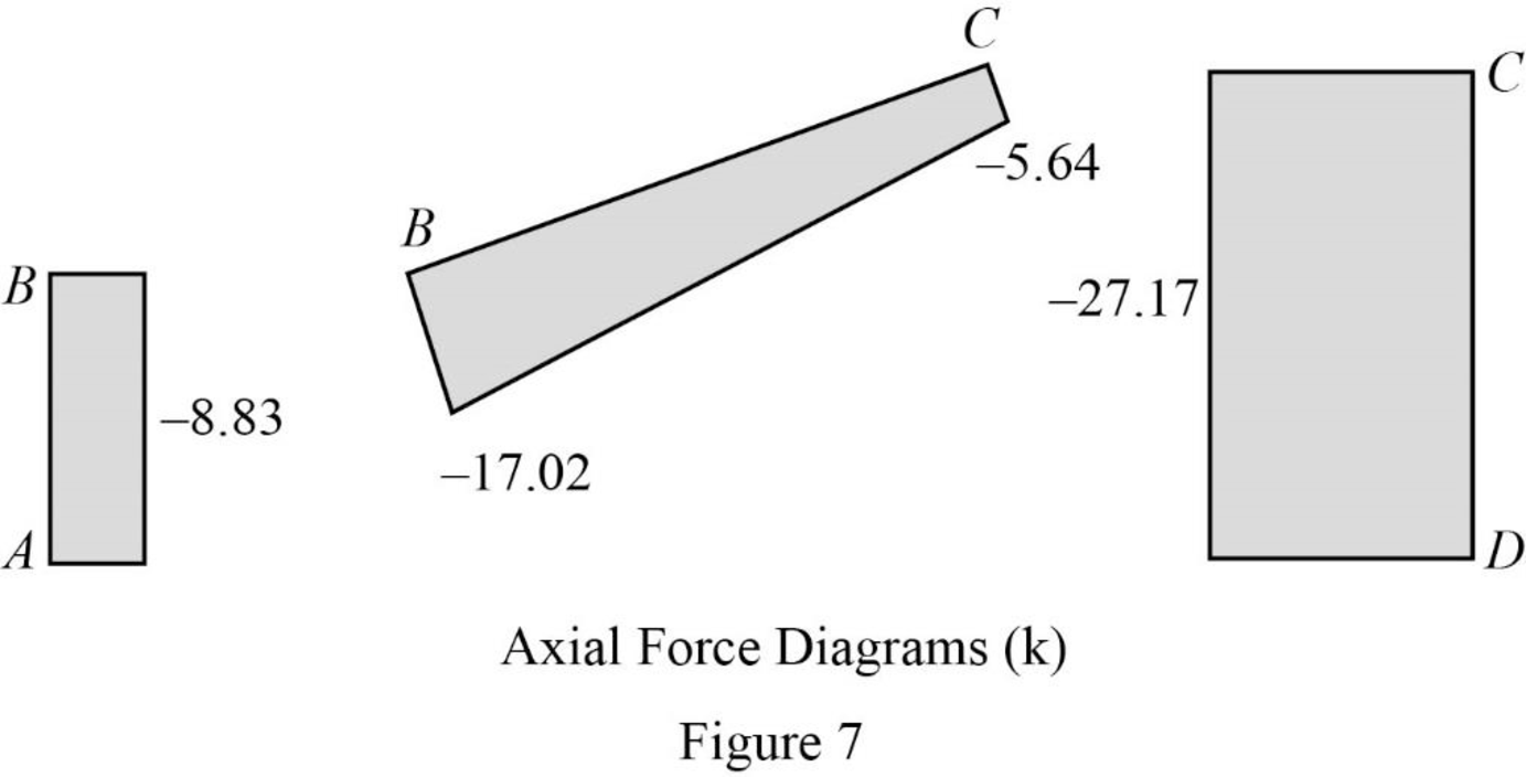
Plot the axial force diagram as in Figure 7.
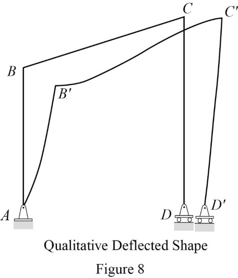
Plot the qualitative deflected shape as in Figure 8.
Want to see more full solutions like this?
Chapter 5 Solutions
Structural Analysis, Si Edition (mindtap Course List)


- Q1: determine the area of steel for the slab that rests on brick walls and is shown in the figure. Use the following data: f'c = 25 MPa, fy = 420 MPa, L.L. = 1.5 kN/m², D.L. = 3 kN/m² (without self-weight). Rate from (1 to 4) your ability to solve the problem 7 m 0.3 m 0.3 marrow_forwardA rigging job calls for lifting a structure that weighs 150 tons. Two cranes are available, one with a rated capacity of 85 tons and the other with a rated capacity of 120 tons. The total weight of the rigging required to make the lift is 15 tons, of which 10 tons is to be carried by the larger craneand 5 tons is to be carried by the smaller crane. If the cranes are to be loaded in proportion to their net capacities, what should be the approximate net load on the 120-ton crane?arrow_forwardI need detailed help solving this exercise from homework of Engineering Mathematics II.I do not really understand how to do, please do it step by step, not that long but clear. Thank you!P.S.: Please do not use AI, thanks!arrow_forward
- I need detailed help solving this exercise from homework of Engineering Mathematics II.I do not really understand how to do, please do it step by step, not that long but clear. Thank you!P.S.: Please do not use AI, thanks!arrow_forwarda) For the truss shown in Fig 2, determine the stiffness matrices of elements 2, 3 and 4 in the in the global co-ordinate system. Assume for each member A = 0.0015 m2 and E = 200 GPa. Indicate the degrees-of freedom in all the stiffness matrices. b) Determine the stiffness matrix of the whole truss in the global co-ordinate system. Clearly indicate the degrees-of freedom numbers in the stiffness matrix. c) Calculate all the nodal displacements and all the member forces of the truss.arrow_forwardI want an answer very quickly, pleasearrow_forward
- I want an answer very quickly, pleasearrow_forwardQ1/ Choose the correct answer for the following: 1- Cantilever retaining walls is suitable for retaining backfill about a- 8m d-4m b- 12m c- 2m e- Any height 2-The shear key is provided to a- Avoid friction behind the wall d- All of the above b- Improve appearance e- None of the above c- Increase passive resistance types of retaining wall may b- Semi-gravity retaining walls d-Counterfort retaining walls be classified as follows: 3- The common a- Gravity retaining walls walls c- Cantilever retaining e- All the mentioned 4-Related to Stability of RW, Which of the following does not represent a potential failure mode for a retaining wall? a-Bearing capacity failure of the foundation soil. b- Wall cracking due to thermal expansion. c- Excessive settlement due to weak soil layer. d- Shear failure within the foundation soil adjacent to the wall. e-Sliding along the base due to insufficient friction. 5- If the desired factor of safety against sliding is not met, which strategy is NOT a…arrow_forwardI want an answer very quickly, pleasearrow_forward
- I need a solution quickly, pleasearrow_forwardI need a solution quickly, pleasearrow_forwardFor the truss shown in Fig 2, determine the nodal displacement and member forces using the stifness method for all elements of the truss. Assume for each member A = 0.0015 m2 and E = 200 GPa please show all workingarrow_forward
