
Concept explainers
Videos
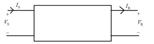
Representing a transmission line by the two-port network, in terms of ABCD parameters, (a) express
(a)
_________ (b)
(a)
The sending end voltage in the form of receiving end parameters.
Answer to Problem 5.1MCQ
Explanation of Solution
Given:
A two port network having ABCD parameter is shown below.

Calculation:
For transmission line, input-output terminal voltage and current in the form of
ABCD parameter is given by,
Hence, from the above relation, sending end voltage is given by
(b)
The sending end current in terms of receiving end parameters.
Answer to Problem 5.1MCQ
Explanation of Solution
Given:
A two port network having ABCD parameter is shown below.
Calculation:
For transmission line, input-output terminal voltage and current in the form of
ABCD parameter in given by,
Hence, from the above relation, sending end current is given by
Want to see more full solutions like this?
Chapter 5 Solutions
Power System Analysis and Design (MindTap Course List)


- Programming Problems 9.28 Assume that a system has a 32-bit virtual address with a 4-KB page size. Write a C program that is passed a virtual address (in decimal) on the command line and have it output the page number and offset for the given address. As an example, your program would run as follows: ./addresses 19986 Your program would output: The address 19986 contains: page number = 4 offset = 3602 Writing this program will require using the appropriate data type to store 32 bits. We encourage you to use unsigned data types as well. Programming Projects Contiguous Memory Allocation In Section 9.2, we presented different algorithms for contiguous memory allo- cation. This project will involve managing a contiguous region of memory of size MAX where addresses may range from 0 ... MAX - 1. Your program must respond to four different requests: 1. Request for a contiguous block of memory 2. Release of a contiguous block of memory 3. Compact unused holes of memory into one single block 4.…arrow_forwardusing r languagearrow_forwardProgramming Problems 9.28 Assume that a system has a 32-bit virtual address with a 4-KB page size. Write a C program that is passed a virtual address (in decimal) on the command line and have it output the page number and offset for the given address. As an example, your program would run as follows: ./addresses 19986 Your program would output: The address 19986 contains: page number = 4 offset = 3602 Writing this program will require using the appropriate data type to store 32 bits. We encourage you to use unsigned data types as well. Programming Projects Contiguous Memory Allocation In Section 9.2, we presented different algorithms for contiguous memory allo- cation. This project will involve managing a contiguous region of memory of size MAX where addresses may range from 0 ... MAX - 1. Your program must respond to four different requests: 1. Request for a contiguous block of memory 2. Release of a contiguous block of memory 3. Compact unused holes of memory into one single block 4.…arrow_forward
- using r languagearrow_forwardWrite a function to compute a Monte Carlo estimate of the Beta(3, 3) cdf, and use the function to estimate F(x) for x = 0.1,0.2,...,0.9. Compare the estimates with the values returned by the pbeta function in R.arrow_forwardWrite a function to compute a Monte Carlo estimate of the Gamma(r = 3, λ = 2) cdf, and use the function to estimate F(x) for x = 0.2, 0.4, . . . , 2.0. Compare the estimates with the values returned by the pgamma function in R.arrow_forward
- using r languagearrow_forwardusing r languagearrow_forwardYou are given a class that processes purchases for an online store. The class receives calls to: • Retrieve the prices for items from a database • Record the sold items • Update the database • Refresh the webpage a. What architectural pattern is suitable for this scenario? Illustrate your answer by drawing a model for the solution, showing the method calls/events. b. Comment on how applying this pattern will impact the modifiability of the system. c. Draw a sequence diagram for the update operation.arrow_forward
- The images I have uploaded are the part 1 to 4 and questions below are continue on the questions uploaded 5. C++ Class Template with Method Stubs #pragma once #include <iostream> #include <string> #include <stdexcept> #include <vector> template <typename T> class HashTable { private: struct Entry { std::string key; T value; bool isOccupied; bool isDeleted; Entry() : key(""), value(), isOccupied(false), isDeleted(false) {} }; Entry* table; size_t capacity; size_t size; double loadFactorThreshold; size_t customHash(const std::string& key) const { size_t hash = 5381; for (char c : key) { hash = ((hash << 5) + hash) + c; } return hash; } size_t probe(const std::string& key, bool forInsert = false) const; void resize(); public: // Constructor HashTable(size_t initialCapacity = 101); // Big…arrow_forwardthis project is NOT for graded(marks) purposes, please help me with the introduction. give me answers for the project. i will include an image explaining everything about the project.arrow_forwardJava Graphics (Bonus In this lab, we'll be practicing what we learned about GUIs, and Mouse events. You will need to implement the following: A GUI with a drawing panel. We can click in this panel, and you will capture those clicks as a Point (see java.awt.Point) in a PointCollection class (you need to build this). The points need to be represented by circles. Below the drawing panel, you will need 5 buttons: O о о ○ An input button to register your mouse to the drawing panel. A show button to paint the points in your collection on the drawing panel. A button to shift all the points to the left by 50 pixels. The x position of the points is not allowed to go below zero. Another button to shift all the points to the right 50 pixels. " The x position of the points cannot go further than the You can implement this GUI in any way you choose. I suggest using the BorderLayout for a panel containing the buttons, and a GridLayout to hold the drawing panel and button panels. Regardless of how…arrow_forward
 Systems ArchitectureComputer ScienceISBN:9781305080195Author:Stephen D. BurdPublisher:Cengage Learning
 Operations Research : Applications and AlgorithmsComputer ScienceISBN:9780534380588Author:Wayne L. WinstonPublisher:Brooks Cole
 Principles of Information Security (MindTap Cours...Computer ScienceISBN:9781337102063Author:Michael E. Whitman, Herbert J. MattordPublisher:Cengage Learning
 Enhanced Discovering Computers 2017 (Shelly Cashm...Computer ScienceISBN:9781305657458Author:Misty E. Vermaat, Susan L. Sebok, Steven M. Freund, Mark Frydenberg, Jennifer T. CampbellPublisher:Cengage Learning
 New Perspectives on HTML5, CSS3, and JavaScriptComputer ScienceISBN:9781305503922Author:Patrick M. CareyPublisher:Cengage Learning
 Fundamentals of Information SystemsComputer ScienceISBN:9781337097536Author:Ralph Stair, George ReynoldsPublisher:Cengage Learning