
EBK PRINCIPLES OF ELECTRIC CIRCUITS
10th Edition
ISBN: 9780134880068
Author: Buchla
Publisher: VST
expand_more
expand_more
format_list_bulleted
Videos
Textbook Question
Chapter 5, Problem 26P
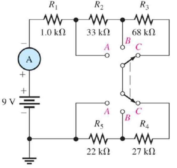
Determine the current measured by the meter in Figure 5–74 for each position of the ganged switch.
Figure 5–74
Expert Solution & Answer
Want to see the full answer?
Check out a sample textbook solution
Students have asked these similar questions
I need help checking if its correct
-E1 + VR1 + VR4 – E2 + VR3 = 0 -------> Loop 1 (a)
R1(I1) + R4(I1 – I2) + R3(I1) = E1 + E2 ------> Loop 1 (b)
R1(I1) + R4(I1) - R4(I2) + R3(I1) = E1 + E2 ------> Loop 1 (c)
(R1 + R3 + R4) (I1) - R4(I2) = E1 + E2 ------> Loop 1 (d)
Now that we have loop 1 equation will procced on finding the equation of I2 current loop. However, a reminder that because we are going in a clockwise direction, it goes against the direction of the current. As such we will get an equation for the matrix that will be:
E2 – VR4 – VR2 + E3 = 0 ------> Loop 2 (a)
-R4(I2 – I1) -R2(I2) = -E2 – E3 ------> Loop 2 (b)
-R4(I2) + R4(I1) - R2(I2) = -E2 – E3 -----> Loop 2 (c)
R4(I1) – (R4 + R2)(I2) = -E2 – E3 -----> Loop 2 (d)
These two equations will be implemented to the matrix formula I = inv(A) * b
R11 R12
(R1 + R3 + R4)
-R4
-R4
R4 + R2
10.2 For each of the following groups of sources, determineif the three sources constitute a balanced source, and if it is,determine if it has a positive or negative phase sequence.(a) va(t) = 169.7cos(377t +15◦) Vvb(t) = 169.7cos(377t −105◦) Vvc(t) = 169.7sin(377t −135◦) V(b) va(t) = 311cos(wt −12◦) Vvb(t) = 311cos(wt +108◦) Vvc(t) = 311cos(wt +228◦) V(c) V1 = 140 −140◦ VV2 = 114 −20◦ VV3 = 124 100◦ V
Apply single-phase equivalency to determine the linecurrents in the Y-D network shown in Fig. P10.13. The loadimpedances are Zab = Zbc = Zca = (25+ j5) W
Chapter 5 Solutions
EBK PRINCIPLES OF ELECTRIC CIRCUITS
Ch. 5 - (a) Show how you would rewire the protoboard in...Ch. 5 - How is the circuit changed when pin 2 and pin 3 in...Ch. 5 - Determine the total resistance in Figure 5-10(a)...Ch. 5 - What is the total resistance for the following...Ch. 5 - Determine the value of R4 in Figure 5-12 if the...Ch. 5 - Find RT for three 1.0 k resistors and two 720 ...Ch. 5 - What is the value of R2 if the highest current is...Ch. 5 - Determine V3 if the polarity of VS2 is reversed in...Ch. 5 - Starting with Equation 5-5, prove that the...Ch. 5 - What is the power in the circuit of Figure 5-48 if...
Ch. 5 - Determine the minimum power rating required for...Ch. 5 - Assume that R1 is shorted In Figure 5-61. What...Ch. 5 - A series circuit can have more than one path for...Ch. 5 - The total resistance of a series circuit can be...Ch. 5 - If two series resistors are different sizes, the...Ch. 5 - If two series resistors are different sizes, the...Ch. 5 - If three equal resistors are used in a voltage...Ch. 5 - There is no valid electrical reason for installing...Ch. 5 - Kirchhoffs voltage law is valid only if a loop...Ch. 5 - Prob. 8TFQCh. 5 - Prob. 9TFQCh. 5 - If point A in a circuit has a voltage of +10 V and...Ch. 5 - Two equal-value resistors are connected in series...Ch. 5 - Prob. 2STCh. 5 - Prob. 3STCh. 5 - When one of four series resistors is removed from...Ch. 5 - Prob. 5STCh. 5 - A 9 V battery is connected across a series...Ch. 5 - While putting four 1.5 V batteries in a four-cell...Ch. 5 - If you measure all the voltage drops and the...Ch. 5 - There are six resistors in a given series circuit...Ch. 5 - A series circuit consists of a 4.7 k, a 5.6 k, and...Ch. 5 - Which of the following series combinations...Ch. 5 - The total power in a certain circuit is 1 W. Each...Ch. 5 - When you connect an ammeter in a series-resistive...Ch. 5 - While checking out a series-resistive circuit, you...Ch. 5 - With a 10 V voltage source connected between...Ch. 5 - For the conditions described in Question 1, the...Ch. 5 - When the switches are in position 1 and a short...Ch. 5 - When the switches are in position 2 and a short...Ch. 5 - If the current shown by one of the milliammeters...Ch. 5 - If the source voltage decreases, the current...Ch. 5 - If the current through R1 increases as a result of...Ch. 5 - If the switch is thrown from position A to...Ch. 5 - If the switch is thrown from position B to...Ch. 5 - If the switch is thrown from position C to...Ch. 5 - If R1 is changed to 1.2 k, the voltage from A to B...Ch. 5 - If R2 and R3 are interchanged, the voltage from A...Ch. 5 - If the source voltage increases from 8 V to 10 V,...Ch. 5 - Connect each set of resistors in Figure 563 in...Ch. 5 - Determine the groupings of resistors in Figure 564...Ch. 5 - Determine the nominal resistance between pins 1...Ch. 5 - Determine the nominal resistance between pins 2...Ch. 5 - On the double-sided PC board in Figure 565,...Ch. 5 - Prob. 6PCh. 5 - Prob. 7PCh. 5 - Calculate RT for each circuit of Figure 566....Ch. 5 - What is the total resistance of twelve 5.6 k...Ch. 5 - Six 56 resistors, eight 100 resistors, and two...Ch. 5 - Prob. 11PCh. 5 - You have the following resistor values available...Ch. 5 - Find the total resistance in Figure 566 if all...Ch. 5 - What is the total resistance from A to B for each...Ch. 5 - What is the current through each resistor in a...Ch. 5 - The current from the source in Figure 569 is 5 mA....Ch. 5 - Show how to connect a voltage source and an...Ch. 5 - Using 1.5 V batteries, a switch, and three lamps,...Ch. 5 - What is the current in each circuit of Figure 570?...Ch. 5 - Determine the voltage drop across each resistor in...Ch. 5 - Three 470 resistors are connected in series with...Ch. 5 - Four equal-value resistors are in series with a 5...Ch. 5 - What is the value of each resistor in Figure 571?...Ch. 5 - Determine VR1, R2, and R3 in Figure 5-72. Figure...Ch. 5 - For the circuit in Figure 573 the meter reads 7.84...Ch. 5 - Determine the current measured by the meter in...Ch. 5 - Refer to Figure 5-75. Assume the green LED drops...Ch. 5 - Refer to Figure 5-76. Assume there is a 2.0 V drop...Ch. 5 - Series aiding is a term sometimes used to describe...Ch. 5 - The term series opposing means that sources are in...Ch. 5 - Determine the total source voltage in each circuit...Ch. 5 - Prob. 32PCh. 5 - Five resistors are in series with a 20 V source....Ch. 5 - Determine the unspecified voltage drop(s) in each...Ch. 5 - In the circuit of Figure 5-79, determine the...Ch. 5 - Find R1, R2, and R3 in Figure 580. Figure 580Ch. 5 - Determine the voltage across R5 for each position...Ch. 5 - The total resistance of a circuit is 560 . What...Ch. 5 - Determine the voltage between points A and B in...Ch. 5 - Determine the voltage with respect to ground for...Ch. 5 - Determine the minimum and maximum voltage from the...Ch. 5 - What is the voltage across each resistor in Figure...Ch. 5 - Prob. 44PCh. 5 - If there are 10 V across R1 in Figure 5-86, what...Ch. 5 - Prob. 46PCh. 5 - Prob. 47PCh. 5 - Five series resistors each handle 50 mW. What is...Ch. 5 - If you double the voltage across a resistor, by...Ch. 5 - If the total resistance of a circuit is halved,...Ch. 5 - What is the total power in the circuit in Figure...Ch. 5 - The following W resistors are in series: 1.2 k,...Ch. 5 - Find RT in Figure 587.Ch. 5 - A certain series circuit consists of a W...Ch. 5 - Determine the voltage at each point with respect...Ch. 5 - In Figure 589, how would you determine the voltage...Ch. 5 - Determine the voltage at each point with respect...Ch. 5 - In Figure 589, what is VAC?Ch. 5 - In Figure 589, what is VCA?Ch. 5 - A string of five series resistors is connected...Ch. 5 - By observing the meters in Figure 590, determine...Ch. 5 - What current would you measure in Figure 590(b) if...Ch. 5 - Table 52 shows the results of resistance...Ch. 5 - You measure 15 k between pins 5 and 6 on the PC...Ch. 5 - In checking out the PC board in Figure 591, you...Ch. 5 - The three groups of series resistors on the PC...
Knowledge Booster


Learn more about
Need a deep-dive on the concept behind this application? Look no further. Learn more about this topic, electrical-engineering and related others by exploring similar questions and additional content below.Similar questions
- 10.8 In the network of Fig. P10.8, Za = Zb = Zc = (25+ j5) W.Determine the line currents.arrow_forwardUsing D flip-flops, design a synchronous counter. The counter counts in the sequence 1,3,5,7, 1,7,5,3,1,3,5,7,.... when its enable input x is equal to 1; otherwise, the counter count 0. Present state Next state x=0 Next state x=1 Output SO 52 S1 1 S1 54 53 3 52 53 S2 56 51 0 $5 5 54 S4 53 0 55 58 57 7 56 56 55 0 57 S10 59 1 58 58 S7 0 59 S12 S11 7 $10 $10 59 0 $11 $14 $13 5 $12 S12 $11 0 513 $15 SO 3 S14 $14 S13 0 $15 515 SO 0 Explain how to get the table step by step with drawing the state diagram and finding the Karnaugh map.arrow_forwardFor the oscillator resonance circuit shown in Fig. (5), derive the oscillation frequency Feedback and open-loop gains. L₁ 5 mH (a) ell +10 V R₁ ww R3 S C2 HH 1 με 1000 pF 100 pF R₂ 1 με RA H (b) +9 V R4 CA 470 pF C₁ R3 HH 1 με R₁ ww L₁ 000 1.5 mH R₂ ww Hi 1 μF L2 m 10 mHarrow_forward
- Expert handwritten solution onlyarrow_forwardB. For the oscillator circuit shown in frequency, feedback and open-loop gains. +10 V name the circuit, derive and find the oscillation P.Av +9 V -000 4₁ 5 mH w R₁ C₂ HH 1 με w 100 pF R₂ T R CA www. 470 pF w ww www 1000 pF HH 1μF C₁ HH 1μF Ra ww HI 4₁ 000 1.5 mH H 4 AF 000 10 mHarrow_forwardI want to check if the current that I have from using the mesh analysis is correct? I1 = 0.214mA I2 = -0.429mAarrow_forward
- I want to find the current by using mesh analysis pleasearrow_forwardI want to find the current by using mesh analysis pleasearrow_forwardR₁ W +10 V R3 +9 V C₂ R₁ CA C₁ 470 pF HH 1000 pF HH 1 με C4 1 μF 1 uF C₁ R₂ R4 100 pF Find Open-loop Jain L₁ 5 mH (a) Av=S,B={" H R₁₂ ✓ ww (b) R₁ L₁ 000 1.5 mH R₂ H 1 uF 12 10 mHarrow_forward
- A) Calculate the efficiency of the test transformer at the resistive loads (X-25%, 50%, 75%, 100%, 125% full load). B) From part (A) draw the plot (efficiency Vs power output) of the transformer. C) Discuss the plot of part (B).arrow_forwarda- Determine fH; and Ho b- Find fg and fr. c- Sketch the frequency response for the high-frequency region using a Bode plot and determine the cutoff frequency. Ans: 277.89 KHz; 2.73 MHz; 895.56 KHz; 107.47 MHz. 14V Cw=5pF Cwo-8pF Coc-12 pF 5.6kQ Ch. 40. pF C-8pF 68kQ 0.47µF Vo 0.82 kQ V₁ B=120 0.47µF www 3.3kQ 10kQ 1.2kQ =20µF Narrow_forwardUsing D flip-flops, design a synchronous counter. The counter counts in the sequence 1,3,5,7, 1,7,5,3,1,3,5,7,.... when its enable input x is equal to 1; otherwise, the counter. This counter is for individual settings only need the state diagram and need the state table to use 16 states from So to S15.arrow_forward
arrow_back_ios
SEE MORE QUESTIONS
arrow_forward_ios
Recommended textbooks for you
 Electricity for Refrigeration, Heating, and Air C...Mechanical EngineeringISBN:9781337399128Author:Russell E. SmithPublisher:Cengage Learning
 EBK ELECTRICAL WIRING RESIDENTIALElectrical EngineeringISBN:9781337516549Author:SimmonsPublisher:CENGAGE LEARNING - CONSIGNMENT
Electricity for Refrigeration, Heating, and Air C...
Mechanical Engineering
ISBN:9781337399128
Author:Russell E. Smith
Publisher:Cengage Learning
EBK ELECTRICAL WIRING RESIDENTIAL
Electrical Engineering
ISBN:9781337516549
Author:Simmons
Publisher:CENGAGE LEARNING - CONSIGNMENT
Introduction to Two-Port Networks; Author: ALL ABOUT ELECTRONICS;https://www.youtube.com/watch?v=ru2ItcD6unI;License: Standard Youtube License