Concept explainers
Sketch the shear and moment curves and label the maximum values of shear and moment, locate points of inflection, and draw the deflected shape.
Explanation of Solution
Apply the sign conventions for calculating reactions using the three equations of equilibrium as shown below.
- For summation of forces along x-direction is equal to zero
- For summation of forces along y-direction is equal to zero
- For summation of moment about a point is equal to zero
Sketch the free body diagram of the beam as shown in Figure 1.
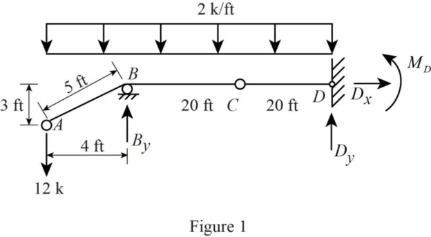
Refer to Figure 1.
Calculate the length of the beam AB as shown in Figure 1.
Use equilibrium equations:
Summation of forces along x-direction is equal to 0.
Summation of forces along y-direction is equal to 0.
Summation of moments about B is equal to 0.
Sketch the free body diagram of the segment CD as shown in Figure 2.
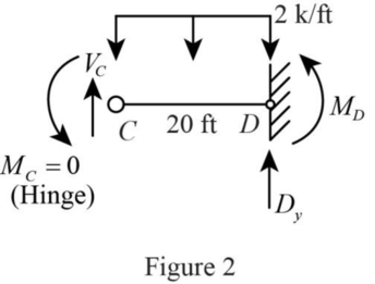
Refer to Figure 2.
Summation of moments about C is equal to 0.
Solving Equations (2) and (3) to get the value of
Substitute 56.6 kips for
Substitute 56.6 kips for
Sketch the free body diagram of the segment AB as shown in Figure 3.
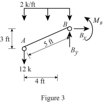
Refer to Figure 3.
Summation of forces along x-direction is equal to 0.
Summation of forces along y-direction is equal to 0.
Summation of moments about B is equal to 0.
Calculate the axial forces as shown below.
Calculate the shearing forces as shown below.
Calculate the shear at each point as shown below.
For segment AB.
For segment BCD.
Calculate the moment at each point as shown below.
For segment AB.
For segment BCD.
Calculate the point of zero shear force as shown below.
Consider a section at a distance x from B.
Sketch the Free Body Diagram of BCD as shown in Figure 4.
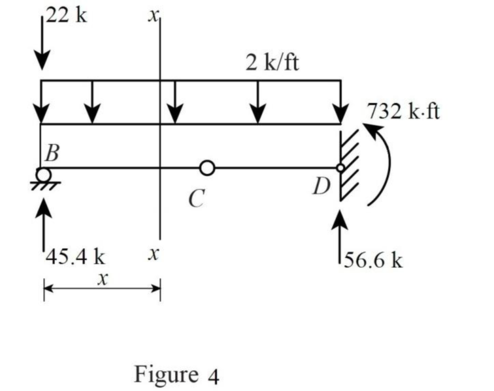
Refer to Figure 4.
Calculate the location of zero shear force as shown below.
Summation of shear at section x is equal to 0.
Maximum bending moment occurs at the point of zero shear.
Point of inflection is the location at which the bending moment changes its sign.
Here the BM is zero sign between BC and CD.
Refer to Figure 4.
Calculate the location of point of inflection where BM is zero as shown below.
Summation of moment at section x-x is equal to 0.
Hence, the point of inflection occurs at C and a distance of 3.4 ft from B.
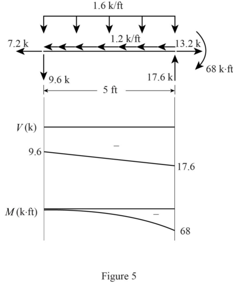
Sketch the shear and moment curves for segment AB as shown in Figure 5.
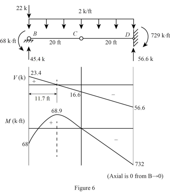
Sketch the shear and moment curves for segment BCD as shown in Figure 6.
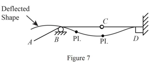
Sketch the deflected shape and the location of points of inflection of the beam as shown in Figure 7.
Want to see more full solutions like this?
Chapter 5 Solutions
Fundamentals of Structural Analysis


- The beam shown in the figure below has continuous lateral support of both flanges. The uniform load is a service load consisting of 70% dead load and 30% live load. The dead load includes the weight of the beam. 6 k/ft +9 18' If A992 steel is used, is a W12 × 35 adequate? For A992 steel: Fy = 50 ksi. bf h For W12 x 35: = 6.31, = 36.2 in., Zx 2tf tw (Express your answers to three significant figures.) a. Use LRFD. Mu Фомп = ft-kips ft-kips A W12 × 35 is -Select- b. Use ASD. Ma = ft-kips Mn ft-kips 26 A W12 × 35 is -Select- = +6→ 51.2 in. 3arrow_forwardVerify the value of Zx for a W10 × 30 that is tabulated in the dimensions and properties tables in Part 1 of the Manual. For W10 × 30: Ag Use the table below. - 8.84 in.2, d 10.5 in. AISC Manual Label y (in.) WT 9 × 25 2.12 WT 8 × 25 1.89 WT 7 × 24 1.35 WT 6 × 25 1.17 WT 5 × 15 1.10 (Express your answer to three significant figures.) Zx = 3 in.arrow_forwarddetermine the horizontal displacement of joint A of the truss. Each member has a cross sectional area of A=300mm2, E=200GPa. Use the method of virtual work and show all workingarrow_forward
- For the frame shown below, determine the vertical displacement at C. Assume that flexural rigidities AB and BC segments are EI and 2EI, respectively. Use the method of virtual work and show all working.arrow_forwardDETERMINE THE BEARINGS OF THE POLYGON/TRAVERSEarrow_forward54 7h de зк +F B + 8 8 Ө 6 A=Sin² E=290ooks for diagonal members A= 30.25in² E = 1800 ksi for hoizontal & Vertical members For Primary Structure revive roller@c, make Da roller and cut BF For redundant structures Redundant " " 2 склес しん Ik @D 3 14 @ BF しん ↑arrow_forward
- A3.2- The 4.5m long cantilever beam is subjected to the specified uniformly distributed dead load 7.0 kN/m (including self-weight) and to the specified uniformly distributed live load 8.0 kN/m. The beam is made of normal density concrete containing maximum 20mm aggregate size with f'c = 25 MPa. Design the shear reinforcement for the beam using U-stirrups and fy = 400 MPa. Figure 2 WDL = 7.0 kN/m WLL=8.0 kN/m 4.5 m 450 mm' 380 mm *250 mm 3-30M Cross-sectionarrow_forwardA3.1- A simply supported beam is subjected to factored concentrated load of 400 kN at mid-span. The beam has a 10m span and a rectangular cross-section with bw = 350mm, effective depth d = 520mm, and total height h = 620mm. a) Ignor the self-weight of the beam and design the required shear reinforcement for the beam. Use 10M U-stirrups. b) Sketch the beam elevation and show the stirrups. Given: The beam is reinforced with 5-25M longitudinal bars f'c = 30 MPa fy = 400 MPa Maximum aggregate size: 20mm Figure 1 P= 400 kN k 5.0 m + 5.0 m 620 mm 520 mm 350 mm + Cross-sectionarrow_forward+ 54 7h de зк +F 8 B 8 Ө 6 For Primary Structure remove and cut BF For redundant structures Redundant " " 2 склес しん Ik @D 3 14 @ BF しん ↑ A=Sin² E=290ooks for diagonal members A= 30.25in² E = 1800 ksi for hoizontal & Vertical members roller@G, make Da rollerarrow_forward
- An urban freeway is to be designed using the following information. AADT = 52,600 veh/day K (proportion of AADT occurring during the peak hour): D (proportion of peak hour traffic traveling in the peak direction): Trucks: 0.11 0.65 8% of peak hour volume PHF = 0.94 Lane width: Shoulder width: Total ramp density: Terrain: 12 ft 10 ft 0.5 interchange/mile; all interchanges are to be cloverleaf interchanges rolling Determine the number of lanes in the peak direction required to provide LOS C. (Assume commuter traffic and assume no RVs.) lanes Show all calculations required. (Calculate your answers for the peak direction only. Enter fy the peak hour volume in veh/h, the free flow speed in mi/h, the demand flow rate in pc/h/In, the mean speed in mi/h, and the density in pc/mi/In.) fHV peak hour volume free flow speed demand flow rate mean speed veh/h mi/h pc/h/In mi/h density pc/mi/Inarrow_forwardThe beam shown in the figure below is a W16 × 31 of A992 steel and has continuous lateral support. The two concentrated loads are service live loads. Neglect the weight of the beam and determine whether the beam is adequate. Suppose that P = 56 k. For W16 x 31: d=15.9 in., t = 0.275 in., h/t = 51.6, and M = M₁ = 203 ft-kip, M/ P P = = Mp/ =135 ft-kip. 6' W16 x 31 a. Use LRFD. Calculate the required moment strength, the allowable shear strength, and the maximum shear. (Express your answers to three significant figures.) = Mu QvVn Vu = = Beam is -Select- b. Use ASD. ft-kip kips kips Calculate the required moment strength, the allowable shear strength, and the maximum shear. (Express your answers to three significant figures.) Ma = Vn/b Va = = Beam is -Select- ft-kip kips kipsarrow_forward***Please answer all parts. They are part of a single question and not different questions altogether. I will like the solution as well. Thank you!arrow_forward

 Structural Analysis (10th Edition)Civil EngineeringISBN:9780134610672Author:Russell C. HibbelerPublisher:PEARSON
 Principles of Foundation Engineering (MindTap Cou...Civil EngineeringISBN:9781337705028Author:Braja M. Das, Nagaratnam SivakuganPublisher:Cengage Learning
 Fundamentals of Structural AnalysisCivil EngineeringISBN:9780073398006Author:Kenneth M. Leet Emeritus, Chia-Ming Uang, Joel LanningPublisher:McGraw-Hill Education
 Traffic and Highway EngineeringCivil EngineeringISBN:9781305156241Author:Garber, Nicholas J.Publisher:Cengage Learning