
Videos
The four components of a block diagram for a linear, time-invariant system.
Answer to Problem 1RQ
Signals, system, summing junction and pick-off points are the four components of a block diagram for a linear, time-invariant system.
Explanation of Solution
Introduction:
Linear time invariant system (LTI system) represents a class of systems which are linear as well as time invariant. It means that for LTI systems the out possess the linear relationship which is same as the linear combination of individual responses. Also, the output does not depend upon the time at which the input is applied. These systems are easy to represent and understand.
To analyse the control system mathematically, a block diagram of the control system is constructed. The basic components of a block diagram for a linear, time-invariant system as follows:
- Signals: Signal is one of the basic components. We have input signals and output signals.
- System: System is one of the most significant components of the block diagram which connects input and output.
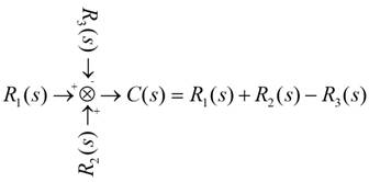
- Summing Junction: Summing junction is the component of the block diagram where the signals get combined as follows.
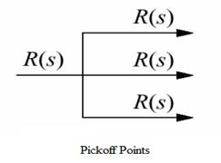
- The pick-off points: Pickoff points are those points where the signal get into different components.
Conclusion:
Thus, four basic components of a block diagram for a linear, time-invariant system are signals, system, summing junction and pick-off points.
Want to see more full solutions like this?
Chapter 5 Solutions
CONTROL SYSTEMS ENGINEERING


- A double thread worm gear has a pitch of 1 1/8 and a pitch diameter of 3 in. It has a coefficient of friction of 0.20 and normal angle (pressure angle) of 14.5o. The worm is supplied by 12 hp at 1200 rpm motor. Find the tangential force on the gear. The worm is left hand threads.arrow_forwardA double thread worm gear has a pitch of 1 1/8 and a pitch diameter of 3 in. It has a coefficient of friction of 0.20 and normal angle (pressure angle) of 14.5o. The worm is supplied by 12 hp at 1200 rpm motor. Find the tangential force on the gear. The worm is left hand threads.arrow_forwardA 2 mm thick, 5L vessel made of nickel is used ot store hydrogen gas at 358 K and 300 kPa. If the total inner surface area of the vessel is 1600 cm^2, determine the rate of gas loss from the nickel vessel via mas diffusion. Also, determine the fraction of the hydrogen lost by mass diffusion after one year of storage.arrow_forward
- < 7:19 The 1st homework 6. Multiple Choice a)唧筒机构 5G31 Which of followings can be th e kinematic diagram of this mechanism? A B Darrow_forward2:54 The 1st homework . 5G 27 b)回转柱塞泵机构 Which of followings can be the kinematic diagram of this mechanis m? A B D Carrow_forwardIm struggling to find the moment about point D. Please explain how to set up and solvearrow_forward
- I keep trying this problem but cant seem to get the sheer right can you help me figure this out please?arrow_forwardThe pillar crane is subjected to the crate having a mass of 1000 kgkg. The boom is held in position shown in (Figure 1).Determine the force in the tie rod ABAB.Determine the horizontal and vertical reactions at the pin support CC.arrow_forwardProblem 7.1 Part A In (Figure 1), F₁ = 550 lb, F2 = 250 lb, and F3 = 340 lb. Figure F F B Part B Determine the shear force at point C. Express your answer to three significant figures and include the appropriate units. Vc=522 ? lb Submit Previous Answers Request Answer × Incorrect; Try Again; 15 attempts remaining Part C Determine the moment at point C. Express your answer to three significant figures and include the appropriate units. 1 of 1 Mc = 1867 F E D lb.ft Submit Previous Answers Request Answer × Incorrect; Try Again; 24 attempts remaining ▸ Part D 6 ft- 4 ft- 4 ft- 6 ft 12 ftarrow_forward
- Sketch h, for Problem 13.64 13 13.65 In Sketch i the tension on the slack side of the left pulley is 20% of that on the tight side. The shaft rotates at 1000 rpm. Select a pair of deep-groove roller bearings to sup- port the shaft for 99% reliability and a life of 20,000 hr. Assume Eq. (13.83) can be used to account for lubricant cleanliness. All length dimensions are in millimeters. b Z 02 0 y 200 500. 187 100 30° B TONE 500 diam 800 N 650 diam 100 N Sketch i, for Problem 13.65 வarrow_forwardProblem 2: Consider the rectangular wood beam below. Use E=1.0. 1. Determine the slope at A. 2. Determine the largest deflection between A and B. Use the elastic curve equation. Show all work. (20%) 3 kN/m A 2.4 m - 50 mm AT 150 mm 0000 - B C 1.2 m→arrow_forwardPlease give a clear solution.arrow_forward
 Elements Of ElectromagneticsMechanical EngineeringISBN:9780190698614Author:Sadiku, Matthew N. O.Publisher:Oxford University Press
 Mechanics of Materials (10th Edition)Mechanical EngineeringISBN:9780134319650Author:Russell C. HibbelerPublisher:PEARSON
 Thermodynamics: An Engineering ApproachMechanical EngineeringISBN:9781259822674Author:Yunus A. Cengel Dr., Michael A. BolesPublisher:McGraw-Hill Education
 Control Systems EngineeringMechanical EngineeringISBN:9781118170519Author:Norman S. NisePublisher:WILEY
 Mechanics of Materials (MindTap Course List)Mechanical EngineeringISBN:9781337093347Author:Barry J. Goodno, James M. GerePublisher:Cengage Learning
 Engineering Mechanics: StaticsMechanical EngineeringISBN:9781118807330Author:James L. Meriam, L. G. Kraige, J. N. BoltonPublisher:WILEY