
Find the axial force, shear force, and bending moments at points A and B of the given beam.
Answer to Problem 1P
The axial force at point A is
The shear force at point A is
The bending moment at point A is
The axial force at point B is
The shear force at point B is
The bending moment at point B is
Explanation of Solution
Given information:
The point load acting at the distance of 5 m from the left support
The inclined point load acting at the distance of 10 m from the left support
The point load acting at the distance of 15 m from the left support
Sign conversion:
Apply the sign convention for calculating the equations of equilibrium as below.
- For the horizontal forces equilibrium condition, take the force acting towards right side as positive
- For the vertical forces equilibrium condition, take the upward force as positive
- For moment equilibrium condition, take the clockwise moment as negative and counter clockwise moment as positive.
Apply the following sign convention for calculating the axial forces, shear and bending moments.
- When the portion of the beam considered is left of the section, then the external force acting to the left are considered as positive.
- When the portion of the beam considered is right of the section, then the external force acting to the right are considered as positive.
- When the portion of the beam considered is left of the section, then the external force acting upward are considered as positive.
- When the portion of the beam considered is right of the section, then the external force acting downward are considered as positive.
- When the portion of the beam considered is left of the section, then the clockwise moments are considered as positive.
- When the portion of the beam considered is right of the section, then the counterclockwise moments are considered as positive.
Calculation:
Draw the free body diagram of the entire beam as in Figure (1).
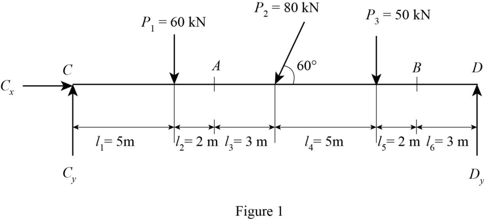
Determine the horizontal force at point C using equilibrium condition.
Substitute 80 kN for
Consider clockwise moment as positive and counter clockwise moment as negative.
Determine the vertical force at the left support using equilibrium condition.
Taking moment about point D.
Substitute 20 m for L, 60 kN for
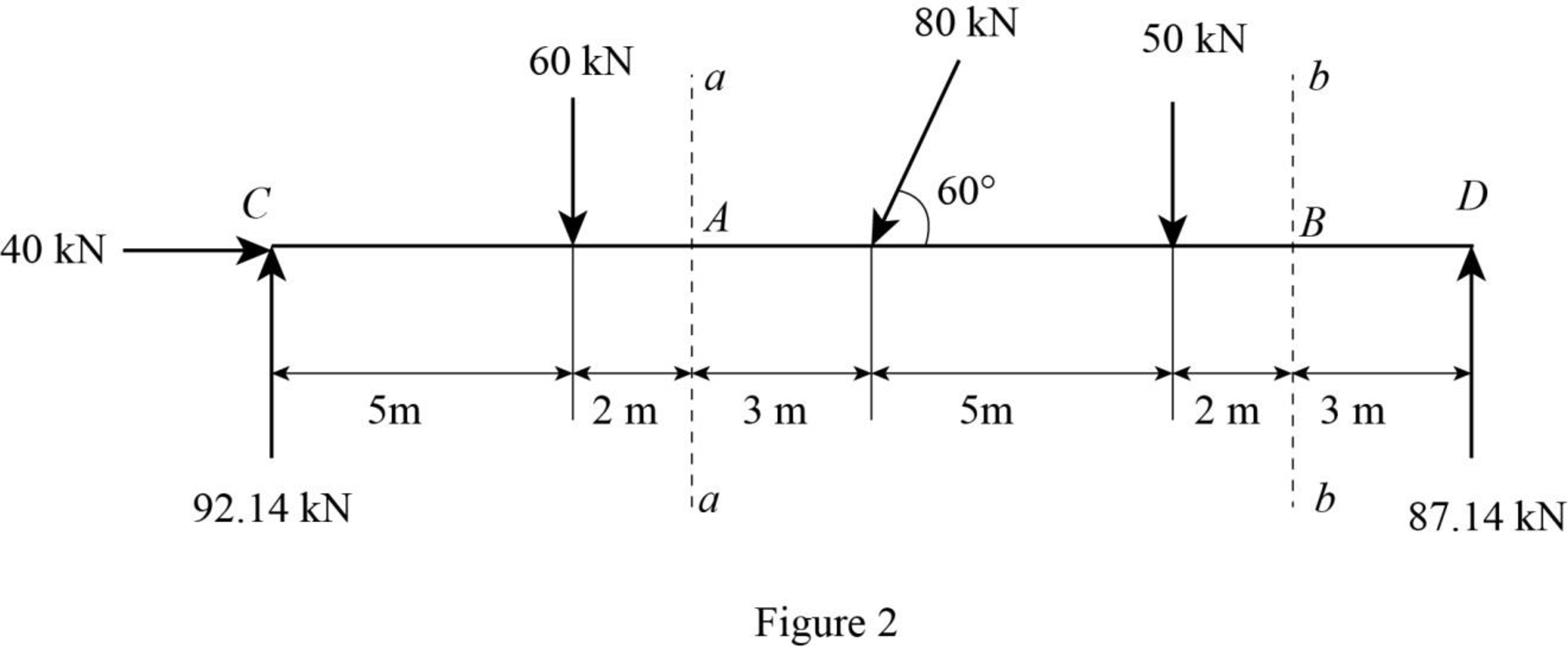
Determine the vertical force at the right support using equilibrium condition.
Substitute 92.14 kN for
Pass the sections aa and bb at points A and B respectively.
Draw the sections aa and bb as in Figure (2).
Consider section aa.
Show the free-body diagram of the left side of the section aa as in Figure 3.
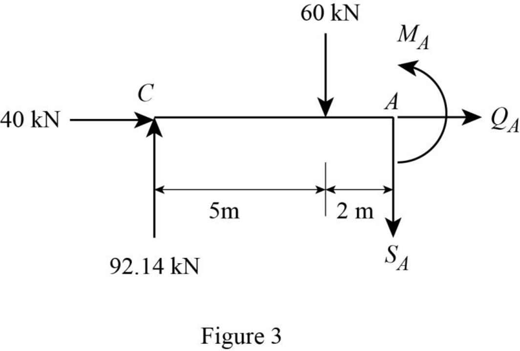
Axial force:
Consider the external forces acting to the left as positive.
Find the axial force at point A by resolving the horizontal equilibrium.
Therefore, the axial force at point A is
Shear force:
Consider the external forces acting upward as positive.
Determine the shear at point A using the relation.
Substitute 92.14 kN for
Therefore, the shear force at point A is
Bending moment:
Consider the clockwise moments of the external forces about A as positive.
Determine the moment at point A equilibrium equations.
Taking moment about point A.
Substitute 92.14 kN for
Therefore, the bending moment at point A is
Consider section bb:
Consider the right side of the section bb for calculation of internal forces.
Show the free-body diagram of the right side of the section bb as in Figure 4.
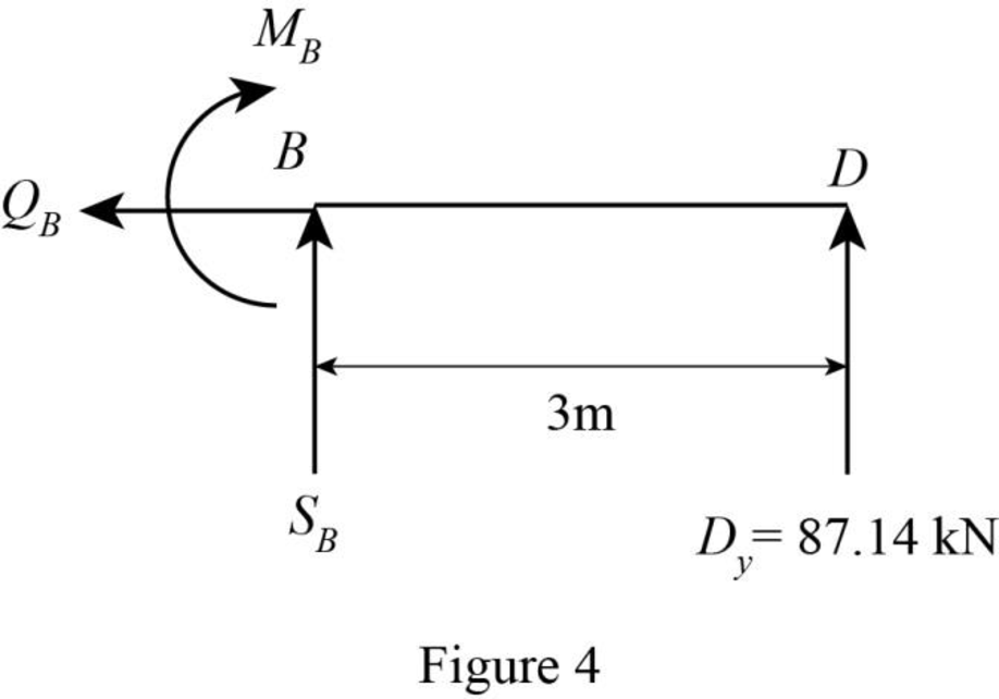
Axial force:
Find the axial force at point B by resolving the horizontal equilibrium.
Therefore, the axial force at point B is
Shear force:
Determine the shear at point B using the relation.
Substitute 87.14 kN for
Therefore, the shear force at point B is
Bending moment:
Consider the counter clockwise moments of the external forces about B as positive.
Determine the moment at point B equilibrium equations.
Taking moment about point B.
Substitute 87.14 kN for
Therefore, the bending moment at point B is
Want to see more full solutions like this?
Chapter 5 Solutions
EBK STRUCTURAL ANALYSIS

- Please draw shear and moment diagrams with provided information.arrow_forwardShow step by step solutionarrow_forwardDraw the shear and the moment diagrams for each of the frames below. If the frame is statically indeterminate the reactions have been provided. Problem 1 (Assume pin connections at A, B and C). 30 kN 2 m 5 m 30 kN/m B 60 kN 2 m 2 m A 22 CO Carrow_forward
- This is an old exam practice question. The answer key says the answer is Pmax = 52.8kN but I am confused how they got that.arrow_forwardF12-45. Car A is traveling with a constant speed of 80 km/h due north, while car B is traveling with a constant speed of 100 km/h due east. Determine the velocity of car B relative to car A. pload Choose a File Question 5 VA - WB VBA V100 111413 + *12-164. The car travels along the circular curve of radius r = 100 ft with a constant speed of v = 30 ft/s. Determine the angular rate of rotation è of the radial liner and the magnitude of the car's acceleration. Probs. 12-163/164 pload Choose a File r = 400 ft 20 ptsarrow_forwardPlease show step by step how to solve this and show formulararrow_forward
- Please solve this question step by step with dia gramarrow_forwardUse the second picture to answer the question, Thank you so much for your help!arrow_forwardP6.16 A compound shaft (Figure P6.16) consists of a titanium alloy [G= 6,200 ksi] tube (1) and a solid stainless steel [G= 11,500 ksi] shaft (2). Tube (1) has a length L₁ = 40 in., an outside diameter D₁ = 1.75 in., and a wall thickness t₁ = 0.125 in. Shaft (2) has a length 42 = 50 in. and a diameter d₂ = 1.25 in. If an external torque TB = 580 lb ft acts at pulley B in the direction shown, calculate the torque Tcrequired at pulley C so that the rotation angle of pulley Crelative to A is zero. B Te (2) TB (1) FIGURE P6.16arrow_forward
- 7.43 Neglecting head losses, determine what horsepower the pump must deliver to produce the flow as shown. Here, the elevations at points A, B, C, and D are 124 ft, 161 ft, 110 ft, and 90 ft, respectively. The nozzle area is 0.10 ft². B Nozzle Water C Problem 7.43arrow_forwardA 1.8m x 1.8m footing is located at a depth of 1 m below the ground surface in a deep deposit of compacted sand (f'= 33 , f' = 28 , γ = 17.5 kN/m). Calculate the ultimate net bearing capacity considering several factors (e.g., shape, depth, and inclination) when the groundwater table is located (a) at 5 m below the footing base, (b) at the ground surface, (c) at the footing base, and (d) at 1.5 m below the footing base. Also, explain the effects of the groundwater levels in the bearing capacities of the footing with your own words. If the information is not given for the calculation, please assume it reasonably.arrow_forward7.18 Determine the discharge in the pipe and the pressure at point B. Neglect head losses. Assume α = 1.0 at all locations. 1.5 m Water B 3.5 m 40 cm diameter -20 cm diameter nozzle Problem 7.18arrow_forward
