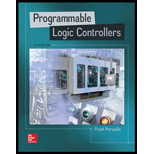
Programmable Logic Controllers
5th Edition
ISBN: 9780073373843
Author: Frank D. Petruzella
Publisher: McGraw-Hill Education
expand_more
expand_more
format_list_bulleted
Concept explainers
Expert Solution & Answer
Chapter 5, Problem 16RQ
Explanation of Solution
a.
Makeup of a ladder logic rung:
- The ladder logic rung refers to the logical representation of physical electrical wiring.
- It includes a set of input conditions which is represented by contact instructions...
Explanation of Solution
b.
Identifying contacts and coil of a rung:
- The contacts and coil of a ladder logic rung are identified by their addresses.
- Each contact or coil is referenced with an address which identifies what is being evaluated and what is being controlled...
Explanation of Solution
c.
Ladder rung having logic continuity:
- The ladder logic rung is said to have continuity when current flow is established in a ladder rung from one side of the power rail to the other...
Expert Solution & Answer
Trending nowThis is a popular solution!

Students have asked these similar questions
I need help to solve a simple problem using Grover’s algorithm, where the solution is not necessarily known beforehand. The problem is a 2×2 binary sudoku with two rules:
• No column may contain the same value twice.
• No row may contain the same value twice.
Each square in the sudoku is assigned to a variable as follows:
We want to design a quantum circuit that outputs a valid solution to this sudoku. While using Grover’s algorithm for this task is not necessarily practical, the goal is to demonstrate how classical decision problems can be converted into oracles for Grover’s algorithm.
Turning the Problem into a Circuit
To solve this, an oracle needs to be created that helps identify valid solutions. The first step is to construct a classical function within a quantum circuit that checks whether a given state satisfies the sudoku rules.
Since we need to check both columns and rows, there are four conditions to verify:
v0 ≠ v1 # Check top row
v2 ≠ v3 # Check bottom row…
using r language
I need help to solve a simple problem using Grover’s algorithm, where the solution is not necessarily known beforehand. The problem is a 2×2 binary sudoku with two rules:
• No column may contain the same value twice.
• No row may contain the same value twice.
Each square in the sudoku is assigned to a variable as follows:
We want to design a quantum circuit that outputs a valid solution to this sudoku. While using Grover’s algorithm for this task is not necessarily practical, the goal is to demonstrate how classical decision problems can be converted into oracles for Grover’s algorithm.
Turning the Problem into a Circuit
To solve this, an oracle needs to be created that helps identify valid solutions. The first step is to construct a classical function within a quantum circuit that checks whether a given state satisfies the sudoku rules.
Since we need to check both columns and rows, there are four conditions to verify:
v0 ≠ v1 # Check top row
v2 ≠ v3 # Check bottom row…
Chapter 5 Solutions
Programmable Logic Controllers
Ch. 5 - What does the memory map for a typical PLC...Ch. 5 - Compare the function of the PLC program and data...Ch. 5 - Prob. 3RQCh. 5 - Prob. 4RQCh. 5 - a. What information is stored in the input image...Ch. 5 - a. What information is stored in the output image...Ch. 5 - Prob. 7RQCh. 5 - List four factors that enter into the length of...Ch. 5 - Prob. 9RQCh. 5 - Prob. 10RQ
Ch. 5 - Prob. 11RQCh. 5 - Answer the following with regard to the Examine If...Ch. 5 - Answer the following with regard to the Examine If...Ch. 5 - Answer the following with regard to the Output...Ch. 5 - A normally closed pushbutton is connected to a PLC...Ch. 5 - Prob. 16RQCh. 5 - Prob. 17RQCh. 5 - Prob. 18RQCh. 5 - Prob. 19RQCh. 5 - Prob. 20RQCh. 5 - Prob. 21RQCh. 5 - Explain the purpose of Windows based programming...Ch. 5 - Prob. 23RQCh. 5 - Prob. 24RQCh. 5 - Prob. 25RQCh. 5 - Prob. 26RQCh. 5 - Assign each of the following discrete input and...Ch. 5 - Prob. 2PCh. 5 - Prob. 3PCh. 5 - Redraw the program shown in Figure 5-57 corrected...Ch. 5 - Redraw the program shown in Figure 5-58 corrected...Ch. 5 - Prob. 6PCh. 5 - Prob. 7PCh. 5 - Prob. 8PCh. 5 - Write the ladder logic program needed to implement...
Knowledge Booster
Learn more about
Need a deep-dive on the concept behind this application? Look no further. Learn more about this topic, computer-science and related others by exploring similar questions and additional content below.Similar questions
- using r languagearrow_forwardI need help to solve a simple problem using Grover’s algorithm, where the solution is not necessarily known beforehand. The problem is a 2×2 binary sudoku with two rules: • No column may contain the same value twice. • No row may contain the same value twice. Each square in the sudoku is assigned to a variable as follows: We want to design a quantum circuit that outputs a valid solution to this sudoku. While using Grover’s algorithm for this task is not necessarily practical, the goal is to demonstrate how classical decision problems can be converted into oracles for Grover’s algorithm. Turning the Problem into a Circuit To solve this, an oracle needs to be created that helps identify valid solutions. The first step is to construct a classical function within a quantum circuit that checks whether a given state satisfies the sudoku rules. Since we need to check both columns and rows, there are four conditions to verify: v0 ≠ v1 # Check top row v2 ≠ v3 # Check bottom row…arrow_forward1 Vo V₁ V3 V₂ V₂ 2arrow_forward
- I need help to solve a simple problem using Grover’s algorithm, where the solution is not necessarily known beforehand. The problem is a 2×2 binary sudoku with two rules: • No column may contain the same value twice. • No row may contain the same value twice. Each square in the sudoku is assigned to a variable as follows: We want to design a quantum circuit that outputs a valid solution to this sudoku. While using Grover’s algorithm for this task is not necessarily practical, the goal is to demonstrate how classical decision problems can be converted into oracles for Grover’s algorithm. Turning the Problem into a Circuit To solve this, an oracle needs to be created that helps identify valid solutions. The first step is to construct a classical function within a quantum circuit that checks whether a given state satisfies the sudoku rules. Since we need to check both columns and rows, there are four conditions to verify: v0 ≠ v1 # Check top row v2 ≠ v3 # Check bottom row…arrow_forwardI need help to solve a simple problem using Grover’s algorithm, where the solution is not necessarily known beforehand. The problem is a 2×2 binary sudoku with two rules: • No column may contain the same value twice. • No row may contain the same value twice. Each square in the sudoku is assigned to a variable as follows: We want to design a quantum circuit that outputs a valid solution to this sudoku. While using Grover’s algorithm for this task is not necessarily practical, the goal is to demonstrate how classical decision problems can be converted into oracles for Grover’s algorithm. Turning the Problem into a Circuit To solve this, an oracle needs to be created that helps identify valid solutions. The first step is to construct a classical function within a quantum circuit that checks whether a given state satisfies the sudoku rules. Since we need to check both columns and rows, there are four conditions to verify: v0 ≠ v1 # Check top row v2 ≠ v3 # Check bottom row…arrow_forwardI need help to solve a simple problem using Grover’s algorithm, where the solution is not necessarily known beforehand. The problem is a 2×2 binary sudoku with two rules: • No column may contain the same value twice. • No row may contain the same value twice. Each square in the sudoku is assigned to a variable as follows: We want to design a quantum circuit that outputs a valid solution to this sudoku. While using Grover’s algorithm for this task is not necessarily practical, the goal is to demonstrate how classical decision problems can be converted into oracles for Grover’s algorithm. Turning the Problem into a Circuit To solve this, an oracle needs to be created that helps identify valid solutions. The first step is to construct a classical function within a quantum circuit that checks whether a given state satisfies the sudoku rules. Since we need to check both columns and rows, there are four conditions to verify: v0 ≠ v1 # Check top row v2 ≠ v3 # Check bottom row…arrow_forward
- Don't use ai to answer I will report you answerarrow_forwardYou can use Eclipse later for program verification after submission. 1. Create an abstract Animal class. Then, create a Cat class. Please implement all the methods and inheritance relations in the UML correctly: Animal name: String # Animal (name: String) + getName(): String + setName(name: String): void + toString(): String + makeSound(): void Cat breed : String age: int + Cat(name: String, breed: String, age: int) + getBreed(): String + getAge (): int + toString(): String + makeSound(): void 2. Create a public CatTest class with a main method. In the main method, create one Cat object and print the object using System.out.println(). Then, test makeSound() method. Your printing result must follow the example output: name: Coco, breed: Domestic short-haired, age: 3 Meow Meowarrow_forwardautomata theory can please wright the exact language it know for example say it knows strings start 0 and end with 1 this is as example also as regular expressionarrow_forward
arrow_back_ios
SEE MORE QUESTIONS
arrow_forward_ios
Recommended textbooks for you
 Systems ArchitectureComputer ScienceISBN:9781305080195Author:Stephen D. BurdPublisher:Cengage LearningProgramming Logic & Design ComprehensiveComputer ScienceISBN:9781337669405Author:FARRELLPublisher:Cengage
 Operations Research : Applications and AlgorithmsComputer ScienceISBN:9780534380588Author:Wayne L. WinstonPublisher:Brooks Cole
 C++ for Engineers and ScientistsComputer ScienceISBN:9781133187844Author:Bronson, Gary J.Publisher:Course Technology Ptr
 Principles of Information Systems (MindTap Course...Computer ScienceISBN:9781285867168Author:Ralph Stair, George ReynoldsPublisher:Cengage Learning
 A Guide to SQLComputer ScienceISBN:9781111527273Author:Philip J. PrattPublisher:Course Technology Ptr

Systems Architecture
Computer Science
ISBN:9781305080195
Author:Stephen D. Burd
Publisher:Cengage Learning

Programming Logic & Design Comprehensive
Computer Science
ISBN:9781337669405
Author:FARRELL
Publisher:Cengage

Operations Research : Applications and Algorithms
Computer Science
ISBN:9780534380588
Author:Wayne L. Winston
Publisher:Brooks Cole

C++ for Engineers and Scientists
Computer Science
ISBN:9781133187844
Author:Bronson, Gary J.
Publisher:Course Technology Ptr

Principles of Information Systems (MindTap Course...
Computer Science
ISBN:9781285867168
Author:Ralph Stair, George Reynolds
Publisher:Cengage Learning

A Guide to SQL
Computer Science
ISBN:9781111527273
Author:Philip J. Pratt
Publisher:Course Technology Ptr