EBK AUTOMOTIVE TECHNOLOGY: A SYSTEMS AP
6th Edition
ISBN: 8220100474392
Author: ERJAVEC
Publisher: Cengage Learning US
expand_more
expand_more
format_list_bulleted
Concept explainers
Videos
Textbook Question
Chapter 49, Problem 1RQ
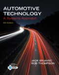
Define camber.
Expert Solution & Answer
To determine
The definition of camber.
Explanation of Solution
Camber is defined as the measure of centerline from the roads surface.
It is also defined as the angle of front and rear wheel from the vertical axis of the wheel, being observed from the front of the car.
When the top surface of the tire tucks inward, it is defined as negative camber. When the tire surface extends outward while turning, it is called a positive camber.
Diagram:
Want to see more full solutions like this?
Subscribe now to access step-by-step solutions to millions of textbook problems written by subject matter experts!
Students have asked these similar questions
Q. After a puncture a driver is attempting to remove a wheel nut by applying a force
of P KN to one end of a wheel brace as shown in Fig. 1. In cross-section the brace
is a hollow steel tube (see section aa) of internal diameter r mm and external
diameter q mm.
wheel
nut
n
Position S
P
m
r
q
Section aa
Fig, 1
(a) Calculate (i) the twisting moment, (ii) the bending moment, and (iii) the shear
force in the brace at position S due to the applied load P.
(b) Calculate (i) the shear stress due to twisting, and (ii) the bending stress at
position S. Note that the shear force will not produce any shear stress at S.
(c) Calculate the maximum shearing stress in the brace at position S using the
Maximum Shear Stress Criterion.
2
Mechanics of Materials 2
Tutorials Portfolio: Exercise 5
(d) If the maximum permissible shear stress in the steel is 200 MPa, determine
the maximum torque that can be applied by the brace without the risk of
failure at S.
Calculate the first 5 Fourier series coefficients (A0-4 and B1-5 ) for the estimated R wave.
Refrigerant-134a is expanded isentropically from 600 kPa and 70°C at the inlet of a steady-flow turbine to 100 kPa at the outlet. The outlet area is 1 m2, and the inlet area is 0.5 m2. Calculate the inlet and outlet velocities when the mass flow rate is 0.65 kg/s. Use the tables for R-134a.
The inlet velocity is m/s.
The outlet velocity is m/s.
Chapter 49 Solutions
EBK AUTOMOTIVE TECHNOLOGY: A SYSTEMS AP
Ch. 49 - Define camber.Ch. 49 - What tire wear pattern will result from excessive...Ch. 49 - What can be caused by excessive negative caster?Ch. 49 - Describe the difference between toe-in and...Ch. 49 - Describe thrust angle and why it is important foi...Ch. 49 - What can cause incorrect toe-out-on-turns?Ch. 49 - In what direction must the bottom of a tire and...Ch. 49 - What is scrub radius and why is it important?Ch. 49 - Prob. 9RQCh. 49 - Describe how caster adjustment may be used to com...
Ch. 49 - Which of the following is a good definition of...Ch. 49 - Prob. 12RQCh. 49 - A 3-degree difference in the SAI angle on each...Ch. 49 - Unequal SAI angles on the left and right sides of...Ch. 49 - While driving straight, a FWD car pulls to the...Ch. 49 - Technician A says that negative caster provides...Ch. 49 - Technician A says that the purpose of the steering...Ch. 49 - Technician A says that the presence of a thrust...Ch. 49 - Technician A says that camber changes as the...Ch. 49 - Technician A says that caster can be adjusted on...Ch. 49 - Technician A says that on FWD vehicles, the front...Ch. 49 - Technician A says that if caster at both wheels is...Ch. 49 - While discussing front-wheel caster: Technician A...Ch. 49 - While performing a prealignment inspection:...Ch. 49 - While performing a prealignment inspection:...
Knowledge Booster


Learn more about
Need a deep-dive on the concept behind this application? Look no further. Learn more about this topic, chemical-engineering and related others by exploring similar questions and additional content below.Similar questions
- A container filled with 70 kg of liquid water at 95°C is placed in a 90-m3 room that is initially at 12°C. Thermal equilibrium is established after a while as a result of heat transfer between the water and the air in the room. Assume the room is at the sea level, well sealed, and heavily insulated. NOTE: This is a multi-part question. Once an answer is submitted, you will be unable to return to this part. Determine the final equilibrium temperature. Use the table containing the ideal gas specific heats of various common gases. The final equilibrium temperature is °C.arrow_forwardSteam at 100 psia and 650°F is expanded adiabatically in a closed system to 10 psia. Determine the work produced, in Btu/lbm, and the final temperature of steam for an isentropic expansion efficiency of 80 percent. Use steam tables. The work produced is Btu/lbm. The final temperature of steam is °F.arrow_forwardComplet the solution : Vavg Ti Te Ts Q hexp Nuexp htheo Re Nutheo Error (m/s) (*C) (*C) (*C) (W) 2.11 18.8 21.3 45.8 2.61 18.5 20.8 46.3arrow_forward
- A 48-kg iron block and a 76-kg copper block, both initially at 80°C, are dropped into a large lake at 15°C. Thermal equilibrium is established after a while as a result of heat transfer between the blocks and the lake water. Determine the total entropy change for this process. The specific heat of iron at room temperature is cp = 0.45 kJ/kg·K. The specific heat of copper at 27°C is cp = 0.386 kJ/kg·K. The total entropy change for this process is kJ/K.arrow_forwardPlease help Air at 4.4 MPa and 500°C is expanded in an adiabatic gas turbine to 0.2 MPa. Calculate the maximum work that this turbine can produce in kJ/kg. Use the table containing the ideal gas specific heats of various common gases. The maximum work that this turbine can produce is kJ/kg.arrow_forwardSaturated water vapor at 150°C is compressed in a reversible steady-flow device to 1150 kPa while its specific volume remains constant. Determine the work required in kJ/kg. Use steam tables. The work required is kJ/kg.arrow_forward
- Three lbm of R-134a is expanded isentropically in a closed system from 100 psia and 100°F to 10 psia. Determine the total heat transfer and the work production for this process. Use the tables for R-134a. The total heat transfer is Btu. The work production for this process is Btu. Three lbm of R-134a is expanded isentropically in a closed system from 100 psia and 100°F to 10 psia. Determine the total heat transfer and the work production for this process. Use the tables for R-134a. The total heat transfer is Btu. The work production for this process is Btu.arrow_forwardOxygen at 300 kPa and 90°C flowing at an average velocity of 3 m/s is expanded in an adiabatic nozzle. What is the maximum velocity of the oxygen at the outlet of this nozzle when the outlet pressure is 60 kPa? Use the table containing the ideal gas specific heats of various common gases. The maximum velocity of the oxygen at the outlet of this nozzle is m/s.arrow_forwardThe well-insulated container shown in the given figure is initially evacuated. The supply line contains air that is maintained at 150 psia and 110°F. The valve is opened until the pressure in the container is the same as the pressure in the supply line. Determine the minimum temperature in the container when the valve is closed. Use the table containing the ideal gas specific heats of various common gases. A valve is shown at the vertical tube. The minimum temperature in the container when the valve is closed is °F.arrow_forward
- During the isothermal heat addition process of a Carnot cycle, 1050 kJ of heat is added to the working fluid from a source at 400°C. NOTE: This is a multi-part question. Once an answer is submitted, you will be unable to return to this part. Determine the total entropy change for the process. The total entropy change for the process is kJ/K.arrow_forwardQuestion 6 What kind of problem would arise if components of the strain tensor were defined as varrow_forwardplease show steps, thanksarrow_forwardarrow_back_iosSEE MORE QUESTIONSarrow_forward_ios
Recommended textbooks for you
 Automotive Technology: A Systems Approach (MindTa...Mechanical EngineeringISBN:9781133612315Author:Jack Erjavec, Rob ThompsonPublisher:Cengage Learning
 Precision Machining Technology (MindTap Course Li...Mechanical EngineeringISBN:9781285444543Author:Peter J. Hoffman, Eric S. Hopewell, Brian JanesPublisher:Cengage Learning
 Automotive TechnologyMechanical EngineeringISBN:9781337794213Author:ERJAVEC, Jack.Publisher:Cengage,
Automotive Technology: A Systems Approach (MindTa...
Mechanical Engineering
ISBN:9781133612315
Author:Jack Erjavec, Rob Thompson
Publisher:Cengage Learning
Precision Machining Technology (MindTap Course Li...
Mechanical Engineering
ISBN:9781285444543
Author:Peter J. Hoffman, Eric S. Hopewell, Brian Janes
Publisher:Cengage Learning
Automotive Technology
Mechanical Engineering
ISBN:9781337794213
Author:ERJAVEC, Jack.
Publisher:Cengage,
composite-materials; Author: Tonya Coffey;https://www.youtube.com/watch?v=Vu6ik-bcKf4;License: Standard youtube license