
MECHANICS OF MATERIALS (LOOSE)-W/ACCESS
10th Edition
ISBN: 9780134583228
Author: HIBBELER
Publisher: PEARSON
expand_more
expand_more
format_list_bulleted
Videos
Textbook Question
Chapter 4.5, Problem 4.67P
The wheel is subjected to a force of 18 kN from the axle. Determine the force in each of the three sp spokes are made of the same material, and each has the same cross-sectional area.

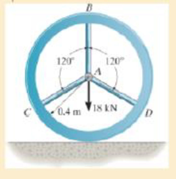
Prob. 4–67
Expert Solution & Answer
Want to see the full answer?
Check out a sample textbook solution
Students have asked these similar questions
A 15 cm-OD pipe is buried with its centerline 1.25 m below the surface of the ground
[k of soil is 0.35 W/(m K)]. An oil having a density of 800 kg/m³ and a specific heat of 2.1 kJ/(kg
K) flows in the pipe at 5.6 L/s. Assuming a ground surface temperature of 5°C and a pipe wall
temperature of 95°C, estimate the length of pipe in which the oil temperature decreases by
5.5°C.
+
Tε = 5ºC
Z= 1.25 m
D= 15 cm
7p=95°C
Find the solution of the following Differential Equations
1) 4y+y=0,
y(0)=2,
y'(0) = 0.
2) y+y=0,
y(0) = A,
y'(0) = B.
3) "+2y'-8y=0,
y(0)=1,
y'(0)=8.
4) y"-2y-3y=0,
y(0)=1,
y'(0)=7.
5) y"-ky' =0,
y(0)=2,
y'(0) =k.
6) y+ky'-2k2y=0,
y(0)=2,
y'(0) = 2k.
7) y'+4y=0,
y(0)=2.8
y+y-17sin(21)
y(0)=-1.
9) y-y'-6y=0,
y(0)=6.
y'(0)=13.
10) y-y=0,
11) y"-4y+4y=0,
y(0)=4,
y'(0) = 0.
y(0) = 2.1,
y'(0)=3.9
12) y+2y+2y=0,
y(0)=1,
y'(0)=-3.
13)
"+7y+12y=21e",
y(0)=3.5,
y'(0)=-10.
14) "+9y=10e",
y(0)=0.
y'(0) = 0.
15) y+3y+2.25y=91³ +64.
y(0)=1,
y'(0) = 31.5
16) "-6y+5y= 29 cos(21),
y(0)=3.2,
y'(0) = 6.2
17) y+2y+2y=0,
y(0)=0,
y'(0)=1.
18) y+2y+17y=0,
y(0)=0,
y'(0)=12.
19) y-4y+5y=0,
y(0)-1,
y'(0) 2.
20) 9y-6y+y=0.
y(0)=3,
y'(0)=1.
21) -2y+10y=0,
y(0)=3,
y'(0)=3.
22) 4y-4y+37y=0,
(0) 3.
y(0) 1.5
23) 4y-8y+5y=0,
(0)-0,
y(0) 1.
24) y+y+1.25y=0,
y(0) 1.
y'(0) -0.5
25) y+y=2 cos(1).
y(0) 2.
y'(0) = 0.
26) -4y+3y=0,
(0)-3,
y'(0) = 7.
27) y+2y+y=e",
y(0)-0.
y'(0) = 0.
29)
28) y+2y-3y-10sinh(2),…
Note:
Please provide a clear, step-by-step simplified handwritten working out (no explanations!), ensuring it is done without any AI involvement. I require an expert-level answer, and I will assess and rate based on the quality and accuracy of your work and refer to the provided image for more clarity. Make sure to double-check everything for correctness before submitting appreciate your time and effort!.
Question:
Chapter 4 Solutions
MECHANICS OF MATERIALS (LOOSE)-W/ACCESS
Ch. 4.2 - In each case, determine the internal normal force...Ch. 4.2 - Determine the internal normal force between...Ch. 4.2 - The post weighs 8kN/m. Determine the internal...Ch. 4.2 - The rod is subjected to an external axial force of...Ch. 4.2 - The rigid beam supports the load of 60 kN....Ch. 4.2 - The 20-mm-diameter A-36 steel rod is subjected to...Ch. 4.2 - Segments AB and CD of the assembly are solid...Ch. 4.2 - The 30-mm-diameter A992 steel rod is subjected to...Ch. 4.2 - If the 20-mm-diameter rod is made of A-36 steel...Ch. 4.2 - The 20-mm-diameter 2014-T6 aluminum rod is...
Ch. 4.2 - The 20-mm-diameter 2014-T6 aluminum rod is...Ch. 4.2 - The A992 steel rod is subjected to the loading...Ch. 4.2 - The copper shaft is subjected to the axial loads...Ch. 4.2 - The composite shaft, consisting of aluminum,...Ch. 4.2 - The composite shaft, consisting of aluminum,...Ch. 4.2 - The 2014-T6 aluminium rod has a diameter of 30 mm...Ch. 4.2 - The A-36 steel drill shaft of an oil well extends...Ch. 4.2 - The truss is made of three A-36 steel members,...Ch. 4.2 - The truss is made of three A-36 steel members,...Ch. 4.2 - The assembly consists of two 10-mm diameter red...Ch. 4.2 - The assembly consists of two 10-mm diameter red...Ch. 4.2 - The load is supported by the four 304 stainless...Ch. 4.2 - The load is supported by the four 304 stainless...Ch. 4.2 - The rigid bar is supported by the pin-connected...Ch. 4.2 - The post is made of Douglas fir and has a diameter...Ch. 4.2 - The post is made of Douglas fir and has a diameter...Ch. 4.2 - The coupling rod is subjected to a force of 5 kip....Ch. 4.2 - The pipe is stuck in the ground so that when it is...Ch. 4.2 - The is made of three pin-connected A992 steel...Ch. 4.2 - The linkage is made of three pin connected A992...Ch. 4.2 - The assembly consists of three titanium...Ch. 4.2 - The rigid beam is supported at its ends by two...Ch. 4.2 - The rigid beam is supported at its ends by two...Ch. 4.2 - The steel bar has the original dimensions shown in...Ch. 4.2 - Determine the relative displacement of one end of...Ch. 4.2 - The assembly consists of two rigid bars that are...Ch. 4.2 - The truss consists of three members, each made...Ch. 4.2 - Solve Prob. 426 when the load P acts vertically...Ch. 4.2 - The observation cage C has a weight of 250 kip and...Ch. 4.2 - The steel bar has the original dimensions shown in...Ch. 4.2 - The ball is truncated at its ends and is used to...Ch. 4.5 - The column is constructed from high-strength...Ch. 4.5 - The column is constructed from high-strength...Ch. 4.5 - The A-36 steel pipe has a 6061-T6 aluminum core....Ch. 4.5 - If column AB is made from high strength precast...Ch. 4.5 - If column AB is made from high strength precast...Ch. 4.5 - Determine the support reactions at the rigid...Ch. 4.5 - If the supports at A and C are flexible and have a...Ch. 4.5 - The load of 2000 lb is to be supported by the two...Ch. 4.5 - The load of 2000 lb is to be supported by the two...Ch. 4.5 - The A-36 steel pipe has an outer radius of 20 mm...Ch. 4.5 - The 10-mm-diameter steel bolt is surrounded by a...Ch. 4.5 - The 10-mm-diameter steel bolt is surrounded by a...Ch. 4.5 - The assembly consists of two red brass C83400...Ch. 4.5 - The rigid beam is supported by the three suspender...Ch. 4.5 - The bolt AB has a diameter of 20 mm and passes...Ch. 4.5 - If the gap between C and the rigid wall at D is...Ch. 4.5 - The support consists of a solid red brass C83400...Ch. 4.5 - If there are n fibers, each having a...Ch. 4.5 - The rigid bar is pinned at A and supported by two...Ch. 4.5 - The rigid bar is pinned at A and supported by two...Ch. 4.5 - The rigid bar is pinned at A and supported by two...Ch. 4.5 - The rigid bar is pinned at A and supported by two...Ch. 4.5 - The 2014-T6 aluminum rod AC is reinforced with the...Ch. 4.5 - The 2014-T6 aluminum rod AC is reinforced with the...Ch. 4.5 - The three suspender bars are made of A992 steel...Ch. 4.5 - The three A-36 steel wires each have a diameter of...Ch. 4.5 - The A-36 steel wires AB and AD each have a...Ch. 4.5 - The post is made from 6061-T6 aluminum and has a...Ch. 4.5 - The post is made from 6061-T6 aluminum and has a...Ch. 4.5 - The bracket is held to the wall using three A-36...Ch. 4.5 - The bracket is held to the wall using three A-36...Ch. 4.5 - If each of the posts has an unloaded length of 1 m...Ch. 4.5 - The rigid bar is supported by the two short white...Ch. 4.5 - The assembly consists of two posts AB and CD each...Ch. 4.5 - The assembly consists of two posts AB and CD each...Ch. 4.5 - The assembly consists of two posts AB and CD each...Ch. 4.5 - The wheel is subjected to a force of 18 kN from...Ch. 4.6 - The C83400-red-brass rod AB and 2014-T6- aluminum...Ch. 4.6 - The assembly has the diameters and material...Ch. 4.6 - The rod is made of A992 steel and has a diameter...Ch. 4.6 - The two cylindrical rod segments are fixed to the...Ch. 4.6 - The two cylindrical rod segments are fixed to the...Ch. 4.6 - The pipe is made of A992 steel and is connected to...Ch. 4.6 - The bronze C86100 pipe has an inner radius of 0.5...Ch. 4.6 - The 40-ft-long A-36 steel rails on a train track...Ch. 4.6 - The device is used to measure a change in...Ch. 4.6 - The bar has a cross-sectional area A, length L,...Ch. 4.6 - When the temperature is at 30C, the A-36 steel...Ch. 4.6 - When the temperature is at 30C, the A-36 steel...Ch. 4.6 - When the temperature is at 30C, the A-36 steel...Ch. 4.6 - The 50-mm-diameter cylinder is made from Am...Ch. 4.6 - The 50-mm-diameter cylinder is made from Am...Ch. 4.6 - The wires AB and AC are made of steel, and wire AD...Ch. 4.6 - The cylinder CD of the assembly is heated from T1...Ch. 4.6 - The cylinder CD of the assembly is heated from T1=...Ch. 4.6 - The metal strap has a thickness t and width w and...Ch. 4.9 - Determine the maximum normal stress developed in...Ch. 4.9 - If the allowable normal stress for the bar is...Ch. 4.9 - The steel bar has the dimensions shown. Determine...Ch. 4.9 - The A-36 steel plate has a thickness of 12 mm. If...Ch. 4.9 - Determine the maximum axial force P that can be...Ch. 4.9 - Determine the maximum normal stress developed in...Ch. 4.9 - The member is to be made from a steel plate that...Ch. 4.9 - The resulting stress distribution along section AB...Ch. 4.9 - The resulting stress distribution along section AB...Ch. 4.9 - Prob. 4.96PCh. 4.9 - The weight is suspended from steel and aluminum...Ch. 4.9 - The bar has a cross-sectional area of 0.5 in2 and...Ch. 4.9 - The distributed loading is applied to the rigid...Ch. 4.9 - The distributed loading is applied to the rigid...Ch. 4.9 - The rigid lever arm is supported by two A-36 steel...Ch. 4.9 - The rigid lever arm is supported by two A-36 steel...Ch. 4.9 - The 300-kip weight is slowly set on the top of a...Ch. 4.9 - The rigid beam is supported by three 25-mm...Ch. 4.9 - The rigid beam is supported by three 25-mm...Ch. 4.9 - The rigid beam is supported by the three posts A,...Ch. 4.9 - The rigid beam is supported by the three posts A,...Ch. 4.9 - The bar having a diameter of 2 in. is fixed...Ch. 4.9 - Determine the elongation of the bar in Prob.4108...Ch. 4.9 - The rigid beam is supported by three A-36 steel...Ch. 4 - The assembly consists of two A992 steel bolts AB...Ch. 4 - The assembly shown consists of two A992 steel...Ch. 4 - The rods each have the same 25-mm diameter and...Ch. 4 - Two A992 steel pipes, each having a...Ch. 4 - The force P is applied to the bar, which is made...Ch. 4 - The 2014-T6 aluminum rod has a diameter of 0.5 in....Ch. 4 - The 2014-T6 aluminum rod has a diameter of 0.5 in....Ch. 4 - The rigid link is supported by a pin at A and two...Ch. 4 - The joint is made from three A992 steel plates...
Knowledge Booster


Learn more about
Need a deep-dive on the concept behind this application? Look no further. Learn more about this topic, mechanical-engineering and related others by exploring similar questions and additional content below.Similar questions
- 4. Block A and B are two different pieces of wood. Determine the minimum dimension for "a", if the shear stress of the wood is 50Mpa. The thickness of the wood is 30cm. 600N Aarrow_forward1. Determine the reaction force at A. 60 kN 5 B 1 m 1 m- -1 m 4 3 m 30 kN marrow_forwardFind the Laplace Transform of the following functions 1) f() cos(ar) Ans. F(s)=7 2ws 2) f() sin(at) Ans. F(s)= s² + a² 3) f(r)-rcosh(at) Ans. F(s)= 2as 4)(t)=sin(at) Ans. F(s)= 2 5) f(1) = 2te' Ans. F(s)= (S-1) 5+2 6) (1) e cos() Ans. F(s) = (+2)+1 7) (1) (Acostẞr)+ Bsin(Br)) Ans. F(s)- A(s+a)+BB (s+a)+B 8) f()-(-)() Ans. F(s)= 9)(1)(1) Ans. F(s): 10) f(r),()sin() Ans. F(s): 11) 2 k 12) 0 13) 0 70 ㄷ.. a 2a 3a 4a 2 3 4 14) f(1)=1, 0<1<2 15) (1) Ksin(t) 0arrow_forward2. Determine the average normal stress developed in rod AB. The mass is 50kg and the diameter of the rod AB is 8mm. B 8 mmarrow_forward2.64 A 2.75-kN tensile load is applied to a test coupon made from 1.6-mm flat steel plate (E = 200 GPa, v = 0.30). Determine the resulting change in (a) the 50-mm gage length, (b) the width of portion AB of the test coupon, (c) the thickness of portion AB, (d) the cross-sectional area of portion AB. 2.75 kN A 12 mm 50 mm B 2.75 kNarrow_forwardProcedure:1- Cartesian system, 2(D)/(3)D,type of support2- Free body diagram3 - Find the support reactions4- If you find a negativenumber then flip the force5- Find the internal force3D\sum Fx=0\sum Fy=0\sum Fz=0\sum Mx=0\sum My=0\Sigma Mz=02D\Sigma Fx=0\Sigma Fy=0\Sigma Mz=05- Use method of sectionand cut the elementwhere you want to findthe internal force andkeep either side of thesectionarrow_forward3. The design of a pump and pipe system has been completed, except for the valves. The system is used to transpor10t water at 120°F through 2 nom sch 40 commercial steel pipe at a required flow rate of 85 gpm. Without the valves, the pump selected has the capability to overcome an additional 18 psi of pressure drop due to the valves and still provide the required flow rate. The pipe/valve joints are threaded. Determine how many 2-inch globe valves can be installed in this pump and pipe system.arrow_forward4. Figure 1 shows a pump and pipe network being used to transport heptane at 120°F to a large, elevated, closed storage tank. The tank is pressurized and maintained at 18 psia. The volumetric flow rate of the heptane is 500 gpm. a. Specify the nominal diameter of the check valve. b. Determine the pump discharge pressure required (psia) to move the heptane through the discharge pipe. Plank = 18 psia Liquid level Large pressurized storage tank 40 ft All pipes are 6-nom sch 40 commercial steel Standard 90° elbows and 180° bend Total length of straight pipe = 115 ft Class 300 swing check valve INH Pump Figure 1: Pressurized storage tank systemarrow_forward2. In a particular section of a fluid system, a 30% ethylene glycol mixture is flowing through a 6- nom xs cast iron pipe at a temperature of 0°C. In this section of piping, the velocity must be maintained in the range 1.5 m/sarrow_forward1. Steam leaves the boiler of a power plant at 5 MPa, 500°C as shown in the following figure. As the steam passes to the turbine, the temperature drops to 496°C before it enters the turbine due to a heat loss through the pipe's insulation. The pressure drop in the pipe connecting the boiler to the turbine is negligible. The steam then passes through an adiabatic turbine and exits at 10 kPa. The turbine has an isentropic efficiency of 85% and is delivering 1000 MW of power. Determine the following. P = 5 MPa T₁ = 500°C Boiler P₁₂ =5 MPa Τ =496°C 7 = 85% W = 1,000 MW P=1 atm To=25°C Turbine 3+ P = 10 kPa a. The heat transfer rate from the pipe connecting the boiler to the turbine (in MW) b. The change in flow exergy rate as the steam flows through the pipe (MW). This represents exergy that is lost to the environment and unavailable for power delivery. Comment on the magnitude of this exergy loss compared to the power delivered by the turbine. What factor(s) would warrant better…arrow_forwardAn aluminum rod of length L = 1m has mass density p = 2700 kg and Young's modulus E = 70 GPa. The rod is fixed at both ends. The exact natural eigenfrequencies of the rod are wexact E = √ ρ for n=1,2,3,. . . . 1. What is the minimum number of linear elements necessary to determine the fundamental frequency w₁ of the system? Discretize the rod in that many elements of equal length, assemble the global system of equations KU = w² MU, and find the fundamental frequency w₁. Compute the relative error e₁ = (w1 - wexact) /w exact Sketch the fundamental mode of vibration. 2. Use COMSOL to solve the same problem. Show the steps necessary to find the fundamental frequency and mode of the rod. What is the relative error using linear elements and a normal mesh?arrow_forwardA ball with a mass of 5.0 kg is hanging from a string and is initially at rest. A bullet with a mass of 10.0 g and a velocity of 200.0 m/s is fired at the ball. The bullet embeds itself inside the ball. How high (h) do the ball and the bullet rise? Gravitational acceleration: g=9.81g = 9.81g=9.81 m/s².arrow_forwardarrow_back_iosSEE MORE QUESTIONSarrow_forward_iosRecommended textbooks for you
 International Edition---engineering Mechanics: St...Mechanical EngineeringISBN:9781305501607Author:Andrew Pytel And Jaan KiusalaasPublisher:CENGAGE L
International Edition---engineering Mechanics: St...Mechanical EngineeringISBN:9781305501607Author:Andrew Pytel And Jaan KiusalaasPublisher:CENGAGE L
Differences between Temporary Joining and Permanent Joining.; Author: Academic Gain Tutorials;https://www.youtube.com/watch?v=PTr8QZhgXyg;License: Standard Youtube License