
Concept explainers
a.
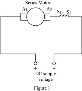
Draw the diagram of series motor.
a.
Explanation of Solution
DC motor:
A DC motor is an electrical rotary machine that is used to convert electrical power into
Series motor:
In the series motor, the field winding and armature winding are connected in series. Since the field and armature winding are in series, it should be large enough to carry the current of the armature circuit. The diagram of series motor is shown in Figure 1. The series field winding is represented as
Conclusion:
Thus, the diagram of series motor is drawn.
b.
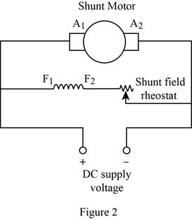
Draw the diagram of shunt motor.
b.
Explanation of Solution
Shunt motor:
In the shunt motor, the field and armature winding are in parallel connection. The rheostat is connected in series with field winding to vary the resistance of field circuit. The diagram of shunt motor is shown in Figure 2. The shunt connected field winding is represented as
Conclusion:
Thus, the diagram of shunt motor is drawn.
c.
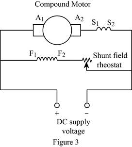
Draw the diagram of compound motor.
c.
Explanation of Solution
Compound motor:
The compound motor has both a series and shunt field winding. The diagram of compound motor is shown in Figure 3.
Conclusion:
Thus, the diagram of compound motor is drawn.
Want to see more full solutions like this?


- Determine X(w) for the given function shown in Figure (1) by applying the differentiation property of the Fourier Transform. Figure (1) -1 x(t)arrow_forwardCan you solve a question with a drawing Determine X(w) for the given function shown in Figure (1) by applying the differentiation property of the Fourier Transform. Figure (1) -1 x(t)arrow_forwardAn inductor has a current flow of 3 A when connected to a 240 V, 60 Hz power line. The inductor has a wire resistance of 15 Find the Q of the inductorarrow_forward
- صورة من s94850121arrow_forwardThe joint density function of two continuous random variables X and Yis: p(x, y) = {Keós (x + y) Find (i) the constant K 0 2 0arrow_forwardShow all the steps please, Solve for the current through R2 if E2 is replaced by a current source of 10mA using superposition theorem. R5=470Ω R2=1000Ω R6=820Ωarrow_forwardPlease solve it by explaining the steps. I am trying to prepare for my exam tomorrow, so any tips and tricks to solve similar problems are highly appreciated. Plus, this is a past exam I am using to prepare.arrow_forwardPlease solve it by explaining the steps. I am trying to prepare for my exam today, so any tips and tricks to solve similar problems are highly appreciated. Plus, this is a past exam I am using to prepare.arrow_forwardIf C is the circle |z|=4 evaluate f f (z)dz for each of the following functions using residue. 1 f(z) = z(z²+6z+4)arrow_forwardIf C is the circle |z|=4 evaluate ff(z)dz for each of the following functions using residue. f(z) z(z²+6z+4)arrow_forwardDetermine X(w) for the given function shown in Figure (1) by applying the differentiation property of the Fourier Transform. 1 x(t) Figure (1) -2 I -1 1 2arrow_forwardPlease solve it by explaining the steps. I am trying to prepare for my exam tomorrow, so any tips and tricks to solve similar problems are highly appreciated. Plus, this is a past exam I am using to prepare.arrow_forwardarrow_back_iosSEE MORE QUESTIONSarrow_forward_ios

 Delmar's Standard Textbook Of ElectricityElectrical EngineeringISBN:9781337900348Author:Stephen L. HermanPublisher:Cengage Learning