(a)
Prove that the reflection coefficient for the given condition is
(a)
Answer to Problem 59CP
Proof for the reflection coefficient for the given condition is
Explanation of Solution
Write the Schrodinger’s equation.
Here,
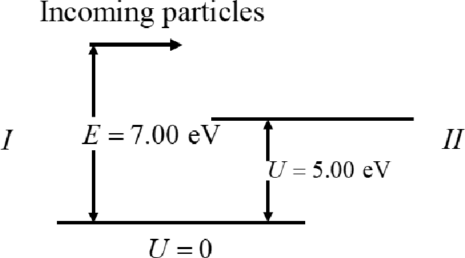
The solutions of the equation I for the region I in the above figure is
The solutions of the equation I for the region II in the above figure is
Here,
Check the solution for the region I satisfies the equation I.
The above equation will be true only if the
Here,
Rewrite the above equation to find the value of
Therefore the equation I is satisfied for the region I.
Check the equation I for the region II.
The above equation will be true only if the
Rewrite the above equation to find the value of
Therefore the equation I is satisfied for the region II.
Then apply the boundary conditions such as matching the function and derivatives at x=0.
From the above equations,
Write the equation for probability.
Conclusion:
Substitute equation VI in VII.
Therefore, the proof for the reflection coefficient for the given condition is
(b)
Find the probability of particle being reflected.
(b)
Answer to Problem 59CP
The probability of particle being reflected is
Explanation of Solution
Write the equation for ration of
Conclusion:
Substitute
Substitute
Therefore, the probability of particle being reflected is
(c)
Find the probability of particle being transmitted.
(c)
Answer to Problem 59CP
The probability of particle being transmitted is
Explanation of Solution
Write the equation for probability of transmitted.
Conclusion:
Substitute
Therefore, the probability of particle being transmitted is
Want to see more full solutions like this?
Chapter 41 Solutions
Physics for Scientists and Engineers with Modern, Revised Hybrid (with Enhanced WebAssign Printed Access Card for Physics, Multi-Term Courses)

- Sketch the harmonic.arrow_forwardFor number 11 please sketch the harmonic on graphing paper.arrow_forward# E 94 20 13. Time a) What is the frequency of the above wave? b) What is the period? c) Highlight the second cycle d) Sketch the sine wave of the second harmonic of this wave % 7 & 5 6 7 8 * ∞ Y U 9 0 0 P 150arrow_forward
- Show work using graphing paperarrow_forwardCan someone help me answer this physics 2 questions. Thank you.arrow_forwardFour capacitors are connected as shown in the figure below. (Let C = 12.0 μF.) a C 3.00 με Hh. 6.00 με 20.0 με HE (a) Find the equivalent capacitance between points a and b. 5.92 HF (b) Calculate the charge on each capacitor, taking AV ab = 16.0 V. 20.0 uF capacitor 94.7 6.00 uF capacitor 67.6 32.14 3.00 µF capacitor capacitor C ☑ με με The 3 µF and 12.0 uF capacitors are in series and that combination is in parallel with the 6 μF capacitor. What quantity is the same for capacitors in parallel? μC 32.14 ☑ You are correct that the charge on this capacitor will be the same as the charge on the 3 μF capacitor. μCarrow_forward
- In the pivot assignment, we observed waves moving on a string stretched by hanging weights. We noticed that certain frequencies produced standing waves. One such situation is shown below: 0 ст Direct Measurement ©2015 Peter Bohacek I. 20 0 cm 10 20 30 40 50 60 70 80 90 100 Which Harmonic is this? Do NOT include units! What is the wavelength of this wave in cm with only no decimal places? If the speed of this wave is 2500 cm/s, what is the frequency of this harmonic (in Hz, with NO decimal places)?arrow_forwardFour capacitors are connected as shown in the figure below. (Let C = 12.0 µF.) A circuit consists of four capacitors. It begins at point a before the wire splits in two directions. On the upper split, there is a capacitor C followed by a 3.00 µF capacitor. On the lower split, there is a 6.00 µF capacitor. The two splits reconnect and are followed by a 20.0 µF capacitor, which is then followed by point b. (a) Find the equivalent capacitance between points a and b. µF(b) Calculate the charge on each capacitor, taking ΔVab = 16.0 V. 20.0 µF capacitor µC 6.00 µF capacitor µC 3.00 µF capacitor µC capacitor C µCarrow_forwardTwo conductors having net charges of +14.0 µC and -14.0 µC have a potential difference of 14.0 V between them. (a) Determine the capacitance of the system. F (b) What is the potential difference between the two conductors if the charges on each are increased to +196.0 µC and -196.0 µC? Varrow_forward
- Please see the attached image and answer the set of questions with proof.arrow_forwardHow, Please type the whole transcript correctly using comma and periods as needed. I have uploaded the picture of a video on YouTube. Thanks,arrow_forwardA spectra is a graph that has amplitude on the Y-axis and frequency on the X-axis. A harmonic spectra simply draws a vertical line at each frequency that a harmonic would be produced. The height of the line indicates the amplitude at which that harmonic would be produced. If the Fo of a sound is 125 Hz, please sketch a spectra (amplitude on the Y axis, frequency on the X axis) of the harmonic series up to the 4th harmonic. Include actual values on Y and X axis.arrow_forward
 Physics for Scientists and Engineers with Modern ...PhysicsISBN:9781337553292Author:Raymond A. Serway, John W. JewettPublisher:Cengage Learning
 Physics for Scientists and Engineers: Foundations...PhysicsISBN:9781133939146Author:Katz, Debora M.Publisher:Cengage Learning
 Principles of Physics: A Calculus-Based TextPhysicsISBN:9781133104261Author:Raymond A. Serway, John W. JewettPublisher:Cengage Learning
 Modern PhysicsPhysicsISBN:9781111794378Author:Raymond A. Serway, Clement J. Moses, Curt A. MoyerPublisher:Cengage Learning
 University Physics Volume 3PhysicsISBN:9781938168185Author:William Moebs, Jeff SannyPublisher:OpenStax
 Glencoe Physics: Principles and Problems, Student...PhysicsISBN:9780078807213Author:Paul W. ZitzewitzPublisher:Glencoe/McGraw-Hill