
Videos
(a)
Find whether the plate is completely, partially, or improperly constrained.
(a)
Answer to Problem 4.59P
The plate in figure 1 is
The plate figure 2 is
The plate figure 3 is
The plate figure 4 is
The plate figure 5 is
The plate figure 6 is
The plate figure 7 is
The plate figure 8 is
Explanation of Solution
Given information:
The size of the identical plates is
Number of plates is 8.
The mass of each plate is
Calculation:
Find the weight (W) of the plate using the relation.
Here, the acceleration due to gravity is g.
Consider the acceleration due to gravity as
Substitute 40 kg for m and
Figure 1:
Show the free-body diagram of the Figure 1.
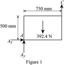
The three reactions in the plate behave like non-concurrent and non-parallel force system.
The plate in figure 1 is
Figure 2:
Show the free-body diagram of the Figure 2.
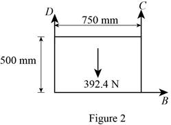
The three reactions in the plate behave like non-concurrent and non-parallel force system.
The plate figure 2 is
Figure 3:
Show the free-body diagram of the Figure 3.
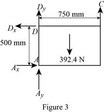
The four reactions in the plate behave like non-concurrent and non-parallel force system.
The plate figure 3 is
Figure 4:
Show the free-body diagram of the Figure 4.
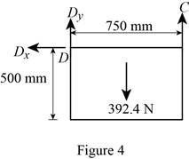
The three reactions in the plate behave like concurrent force system.
The plate figure 4 is
Figure 5:
Show the free-body diagram of the Figure 5.
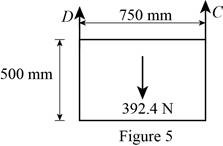
The two reactions in the plate behave like concurrent force system.
The plate figure 5 is
Figure 6:
Show the free-body diagram of the Figure 6.
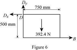
The three reactions in the plate behave like non-concurrent and non-parallel force system.
The plate figure 6 is
Figure 7:
Show the free-body diagram of the Figure 7.
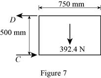
The two reactions in the plate behave like concurrent force system.
The plate figure 7 is
Figure 8:
Show the free-body diagram of the Figure 8.
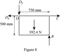
The four reactions in the plate behave like non-concurrent and non-parallel force system.
The plate figure 8 is
(b)
Find whether the reactions are statically determinate or indeterminate.
(b)
Answer to Problem 4.59P
The reactions in figure 1 is
The reactions in figure 2 is
The reactions in figure 3 is
The reactions in figure 4 is
The reactions in figure 5 is
The reactions in figure 6 is
The reactions in figure 7 is
The reactions in figure 8 is
Explanation of Solution
Refer Figure 1:
The equilibrium equations are;
The equilibrium equations are enough to determine the unknown reactions.
The reactions in figure 1 is
Refer Figure 2:
The equilibrium equations are;
The equilibrium equations are enough to determine the unknown reactions.
The reactions in figure 2 is
Refer Figure 3:
The equilibrium equations are;
The equilibrium equations are not enough to determine the unknown reactions.
The reactions in figure 3 is
Refer Figure 4:
The equilibrium equations are;
The equilibrium equations are enough to determine the unknown reactions.
But the plate is improperly constrained and the plate is not in equilibrium.
The reactions in figure 4 is
Refer Figure 5:
The equilibrium equations are;
The equilibrium equations are enough to determine the unknown reactions.
The reactions in figure 5 is
Refer Figure 6:
The equilibrium equations are;
The equilibrium equations are enough to determine the unknown reactions.
The reactions in figure 6 is
Refer Figure 7:
The equilibrium equations are;
The equilibrium equations are enough to determine the unknown reactions.
But the plate is improperly constrained and the plate is not in equilibrium.
The reactions in figure 7 is
Refer Figure 8:
The equilibrium equations are;
The equilibrium equations are not enough to determine the unknown reactions.
The reactions in figure 8 is
(c)
Find whether the equilibrium of the plate is maintained.
(c)
Answer to Problem 4.59P
The reactions in the plate 1 are
The plate 1 is in
The reactions in the plate 2 are
The plate 2 is in
The reactions in the plate 3 are
The plate 3 is in
The plate 4 is in
The reactions in the plate 5 are
The plate 5 is in
The reactions in the plate 6 are
The plate 6 is in
The plate 7 is in
The reactions in the plate 8 are
The plate 8 is in
Explanation of Solution
Refer Figure 1:
The equilibrium equations are;
Take moment about point A.
Resolve the horizontal component of forces.
Resolve the vertical component of forces.
Therefore, the reactions in the plate 1 are
The plate 1 is in
Refer Figure 2:
The equilibrium equations are;
Take moment about point B.
Resolve the horizontal component of forces.
Resolve the vertical component of forces.
Therefore, the reactions in the plate 2 are
The plate 2 is in
Refer Figure 3:
The equilibrium equations are;
Take moment about point A.
Resolve the horizontal component of forces.
Resolve the vertical component of forces.
Therefore, the reactions in the plate 3 are
The plate 3 is in
Refer Figure 4:
The equilibrium equations are;
The moment about point D is not equal to zero.
The plate 4 is in
Refer Figure 5:
The equilibrium equations are;
Take moment about point A.
Resolve the vertical component of forces.
Therefore, the reactions in the plate 5 are
The plate 5 is in
Refer Figure 6:
The equilibrium equations are;
Take moment about point A.
Resolve the vertical component of forces.
Resolve the horizontal component of forces.
Find the resultant force at D;
Find the angle
Therefore, the reactions in the plate 6 are
The plate 6 is in
Refer Figure 7:
The equilibrium equations are;
The plate 7 is in
Refer Figure 8:
The equilibrium equations are;
Take moment about point D.
Resolve the vertical component of forces.
Resolve the horizontal component of forces.
Therefore, the reactions in the plate 8 are
The plate 8 is in
Want to see more full solutions like this?
Chapter 4 Solutions
Vector Mechanics for Engineers: Statics and Dynamics


- For a gas whose equation of state is P(v-b)=RT, the specified heat difference Cp-Cv is equal to which of the following (show all work): (a) R (b) R-b (c) R+b (d) 0 (e) R(1+v/b)arrow_forwardof state is Derive an expression for the specific heat difference of a substance whose equation RT P = v-b a v(v + b)TZ where a and b are empirical constants.arrow_forwardTemperature may alternatively be defined as T = ди v Prove that this definition reduces the net entropy change of two constant-volume systems filled with simple compressible substances to zero as the two systems approach thermal equilibrium.arrow_forward
- Using the Maxwell relations, determine a relation for equation of state is (P-a/v²) (v−b) = RT. Os for a gas whose av Tarrow_forward(◉ Homework#8arrow_forwardHomework#8arrow_forwardBox A has a mass of 15 kilograms and is attached to the 20 kilogram Box B using the cord and pulley system shown. The coefficient of kinetic friction between the boxes and surface is 0.2 and the moment of inertia of the pulley is 0.5 kg * m^ 2. After 2 seconds, how far do the boxes move? A бро Barrow_forwardBox A has a mass of 15 kilograms and is attached to the 20 kilogram Box B using the cord and pulley system shown. The coefficient of kinetic friction between the boxes and surface is 0.2 and the moment of inertia of the pulley is 0.5 kg * m^2. Both boxes are 0.25 m long and 0.25 m high. The cord is attached to the bottom of Box A and the middle of box B. After 2 seconds, how far do the boxes move? A From бро Barrow_forwardHomework#8arrow_forwardSign in PDF Lecture W09.pdf PDF MMB241 - Tutorial L9.pdf File C:/Users/KHULEKANI/Desktop/mmb241/MMB241%20-%20Tutorial%20L9.pdf II! Draw | I│Alla | Ask Copilot + of 4 D Topic: Kinetics of Particles: - Forces in dynamic system, Free body diagram, newton's laws of motion, and equations of motion. TQ1. The 10-kg block is subjected to the forces shown. In each case, determine its velocity when t=2s if v 0 when t=0 500 N F = (201) N 300 N (b) TQ2. The 10-kg block is subjected to the forces shown. In each case, determine its velocity at s-8 m if v = 3 m/s at s=0. Motion occurs to the right. 40 N F = (2.5 s) N 200 N 30 N (b) TQ3. Determine the initial acceleration of the 10-kg smooth collar. The spring has an unstretched length of 1 m. 1 σ Q ☆ Q 6 ا الى ☑arrow_forwardSign in PDF Lecture W09.pdf PDF MMB241 - Tutorial L9.pdf File C:/Users/KHULEKANI/Desktop/mmb241/MMB241%20-%20Tutorial%20L9.pdf II! Draw | I│Alla | Ask Copilot + 4 of 4 | D TQ9. If motor M exerts a force of F (10t 2 + 100) N determine the velocity of the 25-kg crate when t kinetic friction between the crate and the plane are μs The crate is initially at rest. on the cable, where t is in seconds, 4s. The coefficients of static and 0.3 and μk = 0.25, respectively. M 3 TQ10. The spring has a stiffness k = 200 N/m and is unstretched when the 25-kg block is at A. Determine the acceleration of the block when s = 0.4 m. The contact surface between the block and the plane is smooth. 0.3 m F= 100 N F= 100 N k = 200 N/m σ Q Q ☆ ا الى 6 ☑arrow_forwardmy ID# is 016948724 please solve this problem step by steparrow_forwardarrow_back_iosSEE MORE QUESTIONSarrow_forward_iosRecommended textbooks for you
 International Edition---engineering Mechanics: St...Mechanical EngineeringISBN:9781305501607Author:Andrew Pytel And Jaan KiusalaasPublisher:CENGAGE L
International Edition---engineering Mechanics: St...Mechanical EngineeringISBN:9781305501607Author:Andrew Pytel And Jaan KiusalaasPublisher:CENGAGE L