
Videos
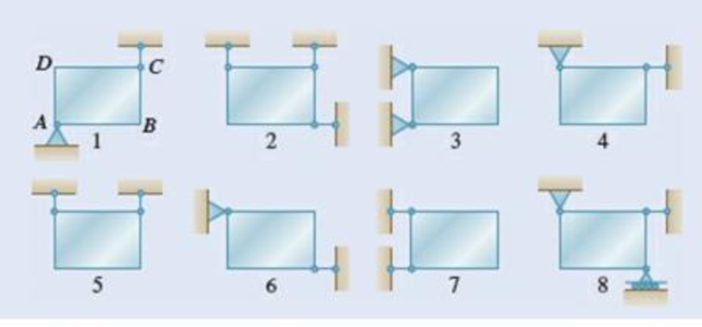
Eight identical 500 × 750-mm rectangular plates, each of mass = 40 kg, are held in a vertical plane as shown. All connections consist of frictionless pins, rollers, or short links. In each case, determine whether (a) the plate is completely, partially, or improperly constrained, (b) the reactions are statically determine or indeterminate, (c) the equilibrium of the plate is maintained the position shown. Also, wherever possible, compute the reactions.
(a)
Find whether the plate is completely, partially, or improperly constrained.
Answer to Problem 4.59P
The plate in figure 1 is
The plate figure 2 is
The plate figure 3 is
The plate figure 4 is
The plate figure 5 is
The plate figure 6 is
The plate figure 7 is
The plate figure 8 is
Explanation of Solution
Given information:
The size of the identical plates is
Number of plates is 8.
The mass of each plate is
Calculation:
Find the weight (W) of the plate using the relation.
Here, the acceleration due to gravity is g.
Consider the acceleration due to gravity as
Substitute 40 kg for m and
Figure 1:
Show the free-body diagram of the Figure 1.
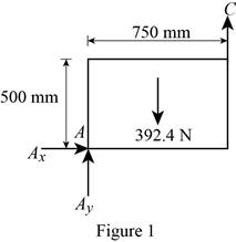
The three reactions in the plate behave like non-concurrent and non-parallel force system.
The plate in figure 1 is
Figure 2:
Show the free-body diagram of the Figure 2.
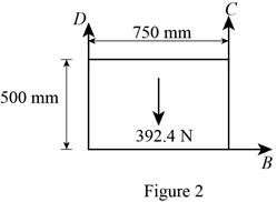
The three reactions in the plate behave like non-concurrent and non-parallel force system.
The plate figure 2 is
Figure 3:
Show the free-body diagram of the Figure 3.
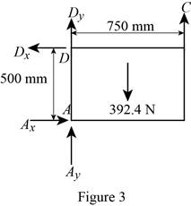
The four reactions in the plate behave like non-concurrent and non-parallel force system.
The plate figure 3 is
Figure 4:
Show the free-body diagram of the Figure 4.
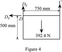
The three reactions in the plate behave like concurrent force system.
The plate figure 4 is
Figure 5:
Show the free-body diagram of the Figure 5.
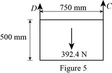
The two reactions in the plate behave like concurrent force system.
The plate figure 5 is
Figure 6:
Show the free-body diagram of the Figure 6.
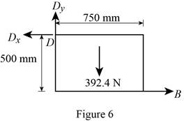
The three reactions in the plate behave like non-concurrent and non-parallel force system.
The plate figure 6 is
Figure 7:
Show the free-body diagram of the Figure 7.

The two reactions in the plate behave like concurrent force system.
The plate figure 7 is
Figure 8:
Show the free-body diagram of the Figure 8.
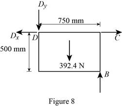
The four reactions in the plate behave like non-concurrent and non-parallel force system.
The plate figure 8 is
(b)
Find whether the reactions are statically determinate or indeterminate.
Answer to Problem 4.59P
The reactions in figure 1 is
The reactions in figure 2 is
The reactions in figure 3 is
The reactions in figure 4 is
The reactions in figure 5 is
The reactions in figure 6 is
The reactions in figure 7 is
The reactions in figure 8 is
Explanation of Solution
Refer Figure 1:
The equilibrium equations are;
The equilibrium equations are enough to determine the unknown reactions.
The reactions in figure 1 is
Refer Figure 2:
The equilibrium equations are;
The equilibrium equations are enough to determine the unknown reactions.
The reactions in figure 2 is
Refer Figure 3:
The equilibrium equations are;
The equilibrium equations are not enough to determine the unknown reactions.
The reactions in figure 3 is
Refer Figure 4:
The equilibrium equations are;
The equilibrium equations are enough to determine the unknown reactions.
But the plate is improperly constrained and the plate is not in equilibrium.
The reactions in figure 4 is
Refer Figure 5:
The equilibrium equations are;
The equilibrium equations are enough to determine the unknown reactions.
The reactions in figure 5 is
Refer Figure 6:
The equilibrium equations are;
The equilibrium equations are enough to determine the unknown reactions.
The reactions in figure 6 is
Refer Figure 7:
The equilibrium equations are;
The equilibrium equations are enough to determine the unknown reactions.
But the plate is improperly constrained and the plate is not in equilibrium.
The reactions in figure 7 is
Refer Figure 8:
The equilibrium equations are;
The equilibrium equations are not enough to determine the unknown reactions.
The reactions in figure 8 is
(c)
Find whether the equilibrium of the plate is maintained.
Answer to Problem 4.59P
The reactions in the plate 1 are
The plate 1 is in
The reactions in the plate 2 are
The plate 2 is in
The reactions in the plate 3 are
The plate 3 is in
The plate 4 is in
The reactions in the plate 5 are
The plate 5 is in
The reactions in the plate 6 are
The plate 6 is in
The plate 7 is in
The reactions in the plate 8 are
The plate 8 is in
Explanation of Solution
Refer Figure 1:
The equilibrium equations are;
Take moment about point A.
Resolve the horizontal component of forces.
Resolve the vertical component of forces.
Therefore, the reactions in the plate 1 are
The plate 1 is in
Refer Figure 2:
The equilibrium equations are;
Take moment about point B.
Resolve the horizontal component of forces.
Resolve the vertical component of forces.
Therefore, the reactions in the plate 2 are
The plate 2 is in
Refer Figure 3:
The equilibrium equations are;
Take moment about point A.
Resolve the horizontal component of forces.
Resolve the vertical component of forces.
Therefore, the reactions in the plate 3 are
The plate 3 is in
Refer Figure 4:
The equilibrium equations are;
The moment about point D is not equal to zero.
The plate 4 is in
Refer Figure 5:
The equilibrium equations are;
Take moment about point A.
Resolve the vertical component of forces.
Therefore, the reactions in the plate 5 are
The plate 5 is in
Refer Figure 6:
The equilibrium equations are;
Take moment about point A.
Resolve the vertical component of forces.
Resolve the horizontal component of forces.
Find the resultant force at D;
Find the angle
Therefore, the reactions in the plate 6 are
The plate 6 is in
Refer Figure 7:
The equilibrium equations are;
The plate 7 is in
Refer Figure 8:
The equilibrium equations are;
Take moment about point D.
Resolve the vertical component of forces.
Resolve the horizontal component of forces.
Therefore, the reactions in the plate 8 are
The plate 8 is in
Want to see more full solutions like this?
Chapter 4 Solutions
Vector Mechanics for Engineers: Statics


- [Q2]: The cost information supplied by the cost accountant is as follows:Sales 20,00 units, $ 10 per unitCalculate the (a/ newsale guantity and (b) new selling price to earn the sameVariable cost $ 6 per unit, Fixed Cost $ 30,000, Profit $ 50,000profit ifi) Variable cost increases by $ 2 per unitil) Fixed cost increase by $ 10,000Ili) Variable cost increase by $ 1 per unit and fixed cost reduces by $ 10,000arrow_forwardcan you please help me perform Visual Inspection and Fractography of the attatched image: Preliminary examination to identify the fracture origin, suspected fatigue striation, and corrosion evidences.arrow_forwardcan you please help[ me conduct Causal Analysis (FTA) on the scenario attatched: FTA diagram which is a fault tree analysis diagram will be used to gain an overview of the entire path of failure from root cause to the top event (i.e., the swing’s detachment) and to identify interactions between misuse, material decay and inspection errors.arrow_forward
- hi can you please help me in finding the stress intensity factor using a k-calcluator for the scenario attathced in the images.arrow_forwardHi, can you please help me .Identify and justify suitable analytical techniques of the scenario below, bearing in mind the kinds of information being handled to reach a conclusion (methodology). A child swing set was discovered to have failed at the fixing at the top of the chains connecting the seat to the top of the swing set. A 12 mm threaded steel bolt, connecting the shackle to the top beam, failed at the start of the threaded region on the linkage closest to the outside side of the swing set . The linkage and bolts were made of electro galvanised mild steel . The rigid bar chain alternatives and fixings were of the same material and appeared to be fitted in accordance with guidelines. The yield strength of the steel used is 260 MPa and the UTS is 380 MPa. The bolt that failed was threaded using a standard thread with a pitch (distance between threads) of 1.75 mm and a depth of approximately 1.1 mm. The swing set in question had been assigned to ‘toddlers’ with the application of…arrow_forwardHi, can you please define and calculate the failure mode of the linkage that failed on the swing (images added) : A child swing set was discovered to have failed at the fixing at the top of the chains connecting the seat to the top of the swing set. A 12 mm threaded steel bolt, connecting the shackle to the top beam, failed at the start of the threaded region on the linkage closest to the outside side of the swing set . The linkage and bolts were made of electro galvanised mild steel . The rigid bar chain alternatives and fixings were of the same material and appeared to be fitted in accordance with guidelines. The yield strength of the steel used is 260 MPa and the UTS is 380 MPa. The bolt that failed was threaded using a standard thread with a pitch (distance between threads) of 1.75 mm and a depth of approximately 1.1 mm. The swing set in question had been assigned to ‘toddlers’ with the application of a caged-type seat. However, the location was within the play area not…arrow_forward
- Page 11-68. The rectangular plate shown is subjected to a uniaxial stress of 2000 psi. Compute the shear stress and the tensile developed on a plane forming an angle of 30° with the longitud axis of the member. (Hint: Assume a cross-sectional area of unity) 2000 psi 2000 psi hparrow_forward11-70. A shear stress (pure shear) of 5000 psi exists on an element. (a) Determine the maximum tensile and compressive stresses caused in the element due to this shear. (b) Sketch the element showing the planes on which the maximum tensile and compressive stresses act.arrow_forward11-20. An aluminum specimen of circular cross section, 0.50 in. in diameter, ruptured under a tensile load of 12,000 lb. The plane of failure was found to be at 48° with a plane perpendicular to the longitudinal axis of the specimen. (a) Compute the shear stress on the failure plane. (b) Compute the maximum tensile stress. (c) Compute the tensile stress on the failure plane. hparrow_forward
- A long flat steel bar 13 mm thick and 120 mm wide has semicircular grooves as shown and carries a tensile load of 50 kN Determine the maximum stress if plate r= 8mm r=21mm r=38mmarrow_forwardProblem 13: F₁ = A =250 N 30% Determine the moment of each of the three forces about point B. F₂ = 300 N 60° 2 m -3 m B 4 m F3=500 Narrow_forward3 kN 3 kN 1.8 kN/m 80 mm B 300 mm D an 1.5 m-1.5 m--1.5 m- PROBLEM 5.47 Using the method of Sec. 5.2, solve Prob. 5.16 PROBLEM 5.16 For the beam and loading shown, determine the maximum normal stress due to bending on a transverse section at C.arrow_forward
 International Edition---engineering Mechanics: St...Mechanical EngineeringISBN:9781305501607Author:Andrew Pytel And Jaan KiusalaasPublisher:CENGAGE L