
EBK ELECTRIC MOTOR CONTROL
10th Edition
ISBN: 9780100784598
Author: Herman
Publisher: YUZU
expand_more
expand_more
format_list_bulleted
Concept explainers
Videos
Textbook Question
Chapter 4, Problem 9SQ
The symbol shown is a
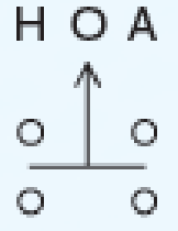
a. double-acting push button.
b. two-position selector switch.
c. three-position selector switch.
d. maintained contact push button.
Expert Solution & Answer

Trending nowThis is a popular solution!

Students have asked these similar questions
Please solve this question step by step and handwritten and do not use chat gpt or ai tools thank you very much!
Please solve question c and d step by step and handwritten and do not use chat gpt or ai tools thank you very much!
Please solve questions d,e,f step by step and handwritten and do not use chat gpt or ai tools thank you very much!
Chapter 4 Solutions
EBK ELECTRIC MOTOR CONTROL
Ch. 4 - Identify the following symbols.Ch. 4 - Electrical symbols usually conform to which...Ch. 4 - What do the following abbreviations stand for? a....Ch. 4 - Single-pole and double-pole switch symbols are...Ch. 4 - The symbol shown is a a. polarized capacitor. b....Ch. 4 - The symbol shown is a a. normally closed float...Ch. 4 - The symbol shown is a(n) a. iron core transformer....Ch. 4 - The symbol shown is a a. normally open pressure...Ch. 4 - The symbol shown is a a. double-acting push...Ch. 4 - If you were installing the circuit in Figure 412,...
Knowledge Booster


Learn more about
Need a deep-dive on the concept behind this application? Look no further. Learn more about this topic, electrical-engineering and related others by exploring similar questions and additional content below.Similar questions
- Please solve this question step by step and handwritten and do not use chat gpt or ai tools thank you very much!arrow_forwardPlease solve question c,d,e step by step and handwritten and do not use chat gpt or ai tools thank you very much!arrow_forwardQ1: Design a logic circuit for the finite-state machine described by the assigned table in Fig. 1: Using D flip-flops. a. b. Using T flip-flops. Present Next State Output State x=0 x=0 YE Y₁Y Y₁Y Z 00 00 01 0 0 от 00 0 0 10 00 10 11 00 10 0arrow_forward
- 2. Using the approximate method, hand sketch the Bode plot for the following transfer functions. a) H(s) = 10 b) H(s) (s+1) c) H(s): = 1 = +1 100 1000 (s+1) 10(s+1) d) H(s) = (s+100) (180+1)arrow_forwardQ4: Write VHDL code to implement the finite-state machine described by the state Diagram in Fig. 1. Fig. 1arrow_forward1. Consider the following feedback system. Bode plot of G(s) is shown below. Phase (deg) Magnitude (dB) -50 -100 -150 -200 0 -90 -180 -270 101 System: sys Frequency (rad/s): 0.117 Magnitude (dB): -74 10° K G(s) Bode Diagram System: sys Frequency (rad/s): 36.8 Magnitude (dB): -99.7 System: sys Frequency (rad/s): 20 Magnitude (dB): -89.9 System: sys Frequency (rad/s): 20 Phase (deg): -143 System: sys Frequency (rad/s): 36.8 Phase (deg): -180 101 Frequency (rad/s) a) Determine the range of K for which the closed-loop system is stable. 102 10³ b) If we want the gain margin to be exactly 50 dB, what is value for K we should choose? c) If we want the phase margin to be exactly 37°, what is value of K we should choose? What will be the corresponding rise time (T) for step-input? d) If we want steady-state error of step input to be 0.6, what is value of K we should choose?arrow_forward
- : Write VHDL code to implement the finite-state machine/described by the state Diagram in Fig. 4. X=1 X=0 solo X=1 X=0 $1/1 X=0 X=1 X=1 52/2 $3/3 X=1 Fig. 4 X=1 X=1 56/6 $5/5 X=1 54/4 X=0 X-O X=O 5=0 57/7arrow_forwardQuestions: Q1: Verify that the average power generated equals the average power absorbed using the simulated values in Table 7-2. Q2: Verify that the reactive power generated equals the reactive power absorbed using the simulated values in Table 7-2. Q3: Why it is important to correct the power factor of a load? Q4: Find the ideal value of the capacitor theoretically that will result in unity power factor. Vs pp (V) VRIPP (V) VRLC PP (V) AT (μs) T (us) 8° pf Simulated 14 8.523 7.84 84.850 1000 29.88 0.866 Measured 14 8.523 7.854 82.94 1000 29.85 0.86733 Table 7-2 Power Calculations Pvs (mW) Qvs (mVAR) PRI (MW) Pay (mW) Qt (mVAR) Qc (mYAR) Simulated -12.93 -7.428 9.081 3.855 12.27 -4.84 Calculated -12.936 -7.434 9.083 3.856 12.32 -4.85 Part II: Power Factor Correction Table 7-3 Power Factor Correction AT (us) 0° pf Simulated 0 0 1 Measured 0 0 1arrow_forwardQuestions: Q1: Verify that the average power generated equals the average power absorbed using the simulated values in Table 7-2. Q2: Verify that the reactive power generated equals the reactive power absorbed using the simulated values in Table 7-2. Q3: Why it is important to correct the power factor of a load? Q4: Find the ideal value of the capacitor theoretically that will result in unity power factor. Vs pp (V) VRIPP (V) VRLC PP (V) AT (μs) T (us) 8° pf Simulated 14 8.523 7.84 84.850 1000 29.88 0.866 Measured 14 8.523 7.854 82.94 1000 29.85 0.86733 Table 7-2 Power Calculations Pvs (mW) Qvs (mVAR) PRI (MW) Pay (mW) Qt (mVAR) Qc (mYAR) Simulated -12.93 -7.428 9.081 3.855 12.27 -4.84 Calculated -12.936 -7.434 9.083 3.856 12.32 -4.85 Part II: Power Factor Correction Table 7-3 Power Factor Correction AT (us) 0° pf Simulated 0 0 1 Measured 0 0 1arrow_forward
arrow_back_ios
SEE MORE QUESTIONS
arrow_forward_ios
Recommended textbooks for you
 Electricity for Refrigeration, Heating, and Air C...Mechanical EngineeringISBN:9781337399128Author:Russell E. SmithPublisher:Cengage Learning
Electricity for Refrigeration, Heating, and Air C...
Mechanical Engineering
ISBN:9781337399128
Author:Russell E. Smith
Publisher:Cengage Learning
Why HIGH VOLTAGE DC power Transmission; Author: ElectroBOOM;https://www.youtube.com/watch?v=DFQG9kuXSxg;License: Standard Youtube License