Concept explainers
Videos
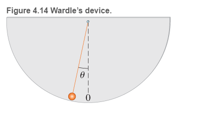
Professor tests airplane takeoff speed D. A. Wardle, a professor of physics from the University of Auckland New Zealand tested the takeoff speed of a commercial airliner. The pilot had insisted that the takeoff speed had to be 232 km /h To perform the testing experiment, Wardle used a pendulum attached to stiff cardboard (Figure 4.14)
Prior to takeoff, when the plane was stationary, he marked the position of the pendulum bob on the cardboard to provide a vertical reference line (the dashed line in Figure 4.14) During the takeoff, he recorded the position of the bob at 5-s intervals. The results are shown in the table.
The information is taken from the article by D. A. Wardle "Measurement of aeroplane takeoff speed and cabin pressure" published in The Physics Teacher, 37, 410-411 (1999).
| t( S) |
|
| 0 | 9.9 |
| 5 | 14.8 |
| 10 | 13.8 |
| 15 | 13.0 |
| 20 | 12.0 |
| 25 | 11.4 |
Using these data, Professor Wardle determined the acceleration at takeoff to be greater than g/4. Then he plotted an acceleration-versus-time graph and used it to find the takeoff speed It turned out to be about 201 km /h. He was very satisfied—the day was windy, and the speed of the breeze was about 15-20 kra /h Thus the takeoff speed predicted by his simple pendulum was 215-220 km /h very close to what the pilot said.
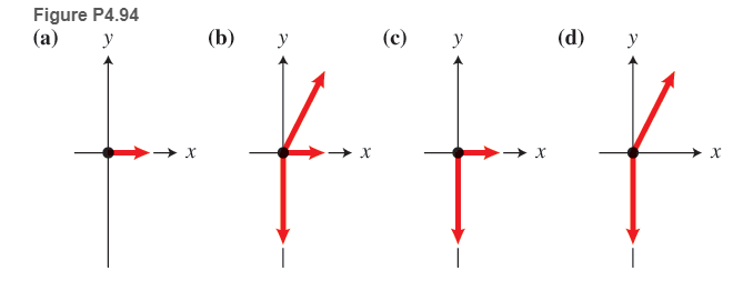
Choose the best force diagram for the pendulum bob as the plane is accelerating down the runway (Figure P4.94).
Want to see the full answer?
Check out a sample textbook solution
Chapter 4 Solutions
COLLEGE PHYSICS:VOL.1
Additional Science Textbook Solutions
Campbell Biology (11th Edition)
Physics for Scientists and Engineers: A Strategic Approach, Vol. 1 (Chs 1-21) (4th Edition)
Chemistry: An Introduction to General, Organic, and Biological Chemistry (13th Edition)
Chemistry (7th Edition)
College Physics: A Strategic Approach (3rd Edition)
Genetic Analysis: An Integrated Approach (3rd Edition)


- You are standing a distance x = 1.75 m away from this mirror. The object you are looking at is y = 0.29 m from the mirror. The angle of incidence is θ = 30°. What is the exact distance from you to the image?arrow_forwardFor each of the actions depicted below, a magnet and/or metal loop moves with velocity v→ (v→ is constant and has the same magnitude in all parts). Determine whether a current is induced in the metal loop. If so, indicate the direction of the current in the loop, either clockwise or counterclockwise when seen from the right of the loop. The axis of the magnet is lined up with the center of the loop. For the action depicted in (Figure 5), indicate the direction of the induced current in the loop (clockwise, counterclockwise or zero, when seen from the right of the loop). I know that the current is clockwise, I just dont understand why. Please fully explain why it's clockwise, Thank youarrow_forwardA planar double pendulum consists of two point masses \[m_1 = 1.00~\mathrm{kg}, \qquad m_2 = 1.00~\mathrm{kg}\]connected by massless, rigid rods of lengths \[L_1 = 1.00~\mathrm{m}, \qquad L_2 = 1.20~\mathrm{m}.\]The upper rod is hinged to a fixed pivot; gravity acts vertically downward with\[g = 9.81~\mathrm{m\,s^{-2}}.\]Define the generalized coordinates \(\theta_1,\theta_2\) as the angles each rod makes with thedownward vertical (positive anticlockwise, measured in radians unless stated otherwise).At \(t=0\) the system is released from rest with \[\theta_1(0)=120^{\circ}, \qquad\theta_2(0)=-10^{\circ}, \qquad\dot{\theta}_1(0)=\dot{\theta}_2(0)=0 .\]Using the exact nonlinear equations of motion (no small-angle or planar-pendulumapproximations) and assuming the rods never stretch or slip, determine the angle\(\theta_2\) at the instant\[t = 10.0~\mathrm{s}.\]Give the result in degrees, in the interval \((-180^{\circ},180^{\circ}]\).arrow_forward
- What are the expected readings of the ammeter and voltmeter for the circuit in the figure below? (R = 5.60 Ω, ΔV = 6.30 V) ammeter I =arrow_forwardsimple diagram to illustrate the setup for each law- coulombs law and biot savart lawarrow_forwardA circular coil with 100 turns and a radius of 0.05 m is placed in a magnetic field that changes at auniform rate from 0.2 T to 0.8 T in 0.1 seconds. The plane of the coil is perpendicular to the field.• Calculate the induced electric field in the coil.• Calculate the current density in the coil given its conductivity σ.arrow_forward
- An L-C circuit has an inductance of 0.410 H and a capacitance of 0.250 nF . During the current oscillations, the maximum current in the inductor is 1.80 A . What is the maximum energy Emax stored in the capacitor at any time during the current oscillations? How many times per second does the capacitor contain the amount of energy found in part A? Please show all steps.arrow_forwardA long, straight wire carries a current of 10 A along what we’ll define to the be x-axis. A square loopin the x-y plane with side length 0.1 m is placed near the wire such that its closest side is parallel tothe wire and 0.05 m away.• Calculate the magnetic flux through the loop using Ampere’s law.arrow_forwardDescribe the motion of a charged particle entering a uniform magnetic field at an angle to the fieldlines. Include a diagram showing the velocity vector, magnetic field lines, and the path of the particle.arrow_forward
 Glencoe Physics: Principles and Problems, Student...PhysicsISBN:9780078807213Author:Paul W. ZitzewitzPublisher:Glencoe/McGraw-Hill
 Principles of Physics: A Calculus-Based TextPhysicsISBN:9781133104261Author:Raymond A. Serway, John W. JewettPublisher:Cengage Learning
 Physics for Scientists and Engineers: Foundations...PhysicsISBN:9781133939146Author:Katz, Debora M.Publisher:Cengage Learning
 University Physics Volume 1PhysicsISBN:9781938168277Author:William Moebs, Samuel J. Ling, Jeff SannyPublisher:OpenStax - Rice University
 College PhysicsPhysicsISBN:9781938168000Author:Paul Peter Urone, Roger HinrichsPublisher:OpenStax College
 Physics for Scientists and Engineers with Modern ...PhysicsISBN:9781337553292Author:Raymond A. Serway, John W. JewettPublisher:Cengage Learning