
CONTROL SYSTEMS ENGINEERING - WILEYPLUS
7th Edition
ISBN: 9781119143277
Author: NISE
Publisher: WILEY
expand_more
expand_more
format_list_bulleted
Concept explainers
Videos
Textbook Question
Chapter 4, Problem 77P
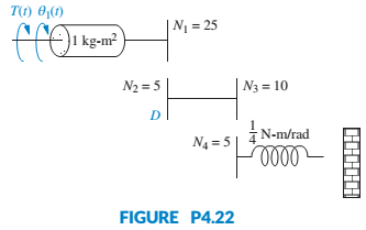
Given the system shown in Figure P4.22, find the damping, D, to yield a 30% overshoot in output angular displacement for a step input in torque. [Section: 4.6]
Expert Solution & Answer
Want to see the full answer?
Check out a sample textbook solution
Students have asked these similar questions
a station is constructed on a concrete slab floor. The heat loss from the floor slab is significant, given the cold environment, and is measured to be 5 kW. The edges of the floor slab are insulated with a 60 mm thickness of cellular glass insulation. The width of this insulation at the floor slab is 0.9 m. To avoid excessive fuel consumption, the station air temperature is maintained at a slightly cool temperature of 18ºC. The station is constructed in a square shape, to keep the surface area to volume ratio low; the horizontal dimensions of the floor of the station are 20 m by 20 m. The number of occupants in the research station varies between 5 and 20, depending on the research workload.a) Determine the design outdoor temperature that was used in designing the research station.b) If the floor dimensions of the station are changed to 15 m by 25 m, would the design outdoor temperature that was used in designing the research station from part (a) change? If so, what would it be?…
Finite Element Analysis
Finite Element Analysis
Chapter 4 Solutions
CONTROL SYSTEMS ENGINEERING - WILEYPLUS
Ch. 4 - Prob. 1RQCh. 4 - What does the performance specification for a...Ch. 4 - Prob. 3RQCh. 4 - In a system with an input and an output, what...Ch. 4 - Prob. 5RQCh. 4 - Prob. 6RQCh. 4 - 7. What is the difference between the natural...Ch. 4 - Prob. 8RQCh. 4 - Prob. 9RQCh. 4 - Prob. 10RQ
Ch. 4 - List five specifications for a second-order...Ch. 4 - Prob. 12RQCh. 4 - What pole locations characterize (1) the...Ch. 4 - Prob. 14RQCh. 4 - How can you justify pole-zero cancellation?Ch. 4 - Prob. 16RQCh. 4 - 17. What is the relationship between , which...Ch. 4 - Name a major advantage of using time-domain...Ch. 4 - Prob. 19RQCh. 4 - What three pieces of information must be given in...Ch. 4 - 21. How can the poles of a system be found from...Ch. 4 - Prob. 1PCh. 4 - Prob. 2PCh. 4 - MATIAB ML 3. Plot the step responses for Problem 2...Ch. 4 - Find the capacitor voltage in the network shown in...Ch. 4 - For the system shown in Figure P4.3, (a) find an...Ch. 4 - Prob. 8PCh. 4 - MATLAB ML 9. Use MATLAB to find the poles of...Ch. 4 - Find the transfer function and poles of the system...Ch. 4 - MATLAB ML 11. Repeat Problem 10 using MATLAB....Ch. 4 - Write the general form of the capacitor voltage...Ch. 4 - Solve for x(t) in the system shown in Figure P4.5...Ch. 4 - Prob. 15PCh. 4 - Prob. 16PCh. 4 - Calculate the exact response of each system of...Ch. 4 - Prob. 18PCh. 4 - Prob. 19PCh. 4 - For each of the second-order systems that follow,...Ch. 4 - MATLAB ML 21. Repeat Problem 20 using MATLAB. Have...Ch. 4 - GUI Tool GUIT
22. Use MATLAB’s LTI Viewer and...Ch. 4 - Prob. 23PCh. 4 - Find the transfer function of a second-order...Ch. 4 - For the system shown in Figure P4.7, do the...Ch. 4 - For the system shown in Figure P4.8, a step torque...Ch. 4 - Prob. 28PCh. 4 - Prob. 29PCh. 4 - Prob. 30PCh. 4 - Prob. 31PCh. 4 - Prob. 32PCh. 4 - Prob. 33PCh. 4 - Prob. 34PCh. 4 - Prob. 35PCh. 4 - Prob. 36PCh. 4 - State Space SS 38. A system is represented by the...Ch. 4 - Prob. 39PCh. 4 - Prob. 40PCh. 4 - State Space SS 41. Given the following system...Ch. 4 - State Space SS 42. Solve the following state...Ch. 4 - Prob. 43PCh. 4 - Prob. 44PCh. 4 - Prob. 46PCh. 4 - Prob. 47PCh. 4 - Prob. 48PCh. 4 - Prob. 53PCh. 4 - Prob. 54PCh. 4 - A MOEMS (optical MEMS) is a MEMS (Micro...Ch. 4 - Prob. 56PCh. 4 - Prob. 59PCh. 4 - Prob. 60PCh. 4 - Prob. 61PCh. 4 - Prob. 63PCh. 4 - Prob. 67PCh. 4 - Figure P4.l6 shows the step response of an...Ch. 4 - Figure P4. I 7 shows the free-body diagrams for...Ch. 4 - Find an equation that relates 2% settling time to...Ch. 4 - Prob. 74PCh. 4 - Prob. 75PCh. 4 - 76. Find J and K in the rotational system shown in...Ch. 4 - Given the system shown in Figure P4.22, find the...Ch. 4 - Prob. 78PCh. 4 - Find M and K, shown in the system of Figure P4.24,...Ch. 4 - If vi(t) is a step voltage in the network shown in...Ch. 4 - Prob. 81PCh. 4 - Prob. 82PCh. 4 - For the circuit shown in Figure P4.26, find the...Ch. 4 - Prob. 84PCh. 4 - Prob. 86P
Knowledge Booster


Learn more about
Need a deep-dive on the concept behind this application? Look no further. Learn more about this topic, mechanical-engineering and related others by exploring similar questions and additional content below.Similar questions
- A small auditorium that can accommodate 30 people allows smoking. The design engineers of the auditorium assume that the smokers each are responsible for an average of 50 micrograms per minute of tobacco smoke being added to the auditorium space. The volumetric flow rate of recirculated room air is 200 cfm. Outdoor air is also supplied, and is mixed with the recirculated room air. The system has a ventilation effectiveness of 80%. In an effort to maintain the level of particulate matter from the tobacco smoke in the auditorium to no more than 5.5 micrograms per cubic foot, filters with an effective efficiency of 90% are added to the ventilation system downstream of the point in the system where outdoor air and recirculated room air are mixed. a) What is the necessary volumetric flow rate (in cfm) for the supply outdoor air? Assume the outdoor air is clean. b) The outdoor air taken into the system becomes contaminated with tobacco smoke due to a leak in an adjacent building’s…arrow_forwardroom to be maintained with a dry-bulb temperature of 72ºF and 30% relative humidity. The room has a sensible heat factor of 0.8 and a total hourly heating load of 200,000 Btu. A flow rate of 1000 cfm of outdoor air (at 20% relative humidity and a dry-bulb temperature of 40ºF) is used. In order to maintain adequate comfort, the supply air to the room is set to a dry-bulb temperature of 120ºF. To humidify the air, steam with a specific enthalpy of 1150 Btu per pound is utilized.Determine the wet bulb temperature, specific enthalpy, and volumetric flow rate of the supply air to the room. Evaluate the increase in dry-bulb temperature as the air is sensibly heated, and the mass flow rate (in lb/hr) of steam required during the latent heating of the air. Calculate the heat added to the room during sensible heating (i.e., excluding humidification).arrow_forwardPlease can you help with the attached question? Many thanksarrow_forward
- Which of the following sequences converge and which diverge? 20) an = 21) a = n! 106 1/(Inn) 3n+1 " 22) a = 3n-1 1/n x" 23) a = , x>0 2n+1 3" x 6" 24) an 25) a, = tanh(n) = 2" xn! n² 1 26) a = sin 2n-1 n 27) a = tan(n) 1 28) a = 1 3 ++ (Inn) 200 2" 29) an n 30) =n-√√n²-n 1"1 31) a == dx nixarrow_forwardWhich of the following sequences converge and which diverge? n+1 6) a = 1- 2n (-1)+1 7) a = 2n-1 2n 8) an = n+1 1 9) a = sin + 2 n sin n 10) a = n 11) an = 12) a = 13) an 14) an 15) an 16) an n 2" In(n+1) = 81/n n n =(1+7)" = = 10n 3 n 1/n 17) an = In n 1/n n' 18) a =√4"narrow_forwardQu 3 Nickel (Ni) single crystal turbine blades burn less fuel at higher temperatures because blades are grown on [110] closed packed direction. Nickel (Ni) at 20°C is FCC, and has an atomic radius, R, of 0.125 nm. Draw a reduced-sphere unit cell for this crystal and draw and label the vector [I 10], starting from the origin (0, 0, 0). a) Calculate the length of the vector [| 10] in nanometers. Express your answer in nanometers to one significant figure. b) Calculate the linear density of Nickel in the [| 1 0] direction in [atom/nm]. Express your answer in atoms/nm to one significant figure. show all work problemsarrow_forward
- handwritten-solutions, please!arrow_forwardhandwritten-solutions, please!arrow_forwardRequired information An eccentric force P is applied as shown to a steel bar of 25 × 90-mm cross section. The strains at A and B have been measured and found to be εΑ = +490 μ εB=-70 μ Know that E = 200 GPa. 25 mm 30 mm 90 mm 45 mm B Determine the distance d. The distance dis 15 mm mm.arrow_forward
- handwritten-solutions, please!arrow_forwardhandwritten-solutions, please!arrow_forward! Required information Assume that the couple shown acts in a vertical plane. Take M = 25 kip.in. r = 0.75 in. A B 4.8 in. M 1.2 in. [1.2 in. Determine the stress at point B. The stress at point B is ksi.arrow_forward
arrow_back_ios
SEE MORE QUESTIONS
arrow_forward_ios
Recommended textbooks for you
 Elements Of ElectromagneticsMechanical EngineeringISBN:9780190698614Author:Sadiku, Matthew N. O.Publisher:Oxford University Press
 Mechanics of Materials (10th Edition)Mechanical EngineeringISBN:9780134319650Author:Russell C. HibbelerPublisher:PEARSON
 Thermodynamics: An Engineering ApproachMechanical EngineeringISBN:9781259822674Author:Yunus A. Cengel Dr., Michael A. BolesPublisher:McGraw-Hill Education
 Control Systems EngineeringMechanical EngineeringISBN:9781118170519Author:Norman S. NisePublisher:WILEY
 Mechanics of Materials (MindTap Course List)Mechanical EngineeringISBN:9781337093347Author:Barry J. Goodno, James M. GerePublisher:Cengage Learning
 Engineering Mechanics: StaticsMechanical EngineeringISBN:9781118807330Author:James L. Meriam, L. G. Kraige, J. N. BoltonPublisher:WILEY
Elements Of Electromagnetics
Mechanical Engineering
ISBN:9780190698614
Author:Sadiku, Matthew N. O.
Publisher:Oxford University Press
Mechanics of Materials (10th Edition)
Mechanical Engineering
ISBN:9780134319650
Author:Russell C. Hibbeler
Publisher:PEARSON
Thermodynamics: An Engineering Approach
Mechanical Engineering
ISBN:9781259822674
Author:Yunus A. Cengel Dr., Michael A. Boles
Publisher:McGraw-Hill Education
Control Systems Engineering
Mechanical Engineering
ISBN:9781118170519
Author:Norman S. Nise
Publisher:WILEY
Mechanics of Materials (MindTap Course List)
Mechanical Engineering
ISBN:9781337093347
Author:Barry J. Goodno, James M. Gere
Publisher:Cengage Learning
Engineering Mechanics: Statics
Mechanical Engineering
ISBN:9781118807330
Author:James L. Meriam, L. G. Kraige, J. N. Bolton
Publisher:WILEY
Ch 2 - 2.2.2 Forced Undamped Oscillation; Author: Benjamin Drew;https://www.youtube.com/watch?v=6Tb7Rx-bCWE;License: Standard youtube license