Logic gate:
- Logic gate is an electronic circuit that is used to take logical decisions based on the input.
- It contains one or more number of inputs and one output.
- The working of logic gate is based on the binary principle that has two states either logic 0 or logic 1.
- The output of logic gate is produced when it satisfies any of its logic conditions.
- The logic condition depends upon the type of the gates and the number of inputs.
- The primary logic gates include AND, OR and NOT and the combinations of these gates are used to implement any of the other logic gates.
AND gate:
- The AND gate refers to a logic gate whose output will be HIGH only when all the inputs are HIGH.
- The output of AND gate will be LOW when any one of its input is LOW.
- The symbol to represent AND gate is given below:
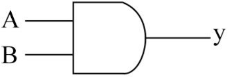
- The truth table for AND gate is as follows:
| INPUT A | INPUT B | OUTPUT Y |
| 0 | 0 | 0 |
| 0 | 1 | 0 |
| 1 | 0 | 0 |
| 1 | 1 | 1 |
OR gate:
- The OR gate refers to a logic gate whose output will be HIGH when any one of its inputs are HIGH.
- The output of AND gate will be LOW when both the inputs are LOW.
- The symbol to represent OR gate is given below:
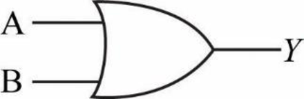
- The truth table for OR gate is as follows:
| INPUT A | INPUT B | OUTPUT Y |
| 0 | 0 | 0 |
| 0 | 1 | 1 |
| 1 | 0 | 1 |
| 1 | 1 | 1 |
NOT gate:
- The NOT gate refers to a logic gate whose output will be HIGH when it’s input is LOW and whose output will be LOW when it’s input is HIGH.
- The symbol to represent NOT gate is given below:
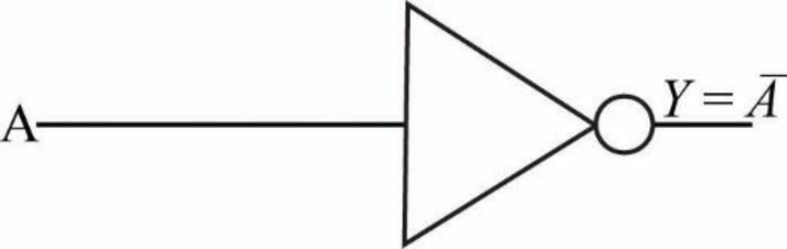
- The truth table for NOT gate is as follows:
| INPUT A | OUTPUT Y |
| 0 | 1 |
| 1 | 0 |
Explanation of Solution
b.
Logic gate circuit:
The logic gate circuit for the given Boolean expression
Explanation:
In the above given logic gate circuit,
- The inputs “A” and “B” are connected to logic AND gate and the corresponding output will be (AB)
Explanation of Solution
c.
Logic gate circuit:
The logic gate circuit for the given Boolean expression
Explanation:
In the above given logic gate circuit,
- The inputs “A” and “B” are connected to logic OR gate and the corresponding output will be (A+B).
- The input “C” is connected to logic NOT gate and the corresponding output will be “
Explanation of Solution
d.
Logic gate circuit:
The logic gate circuit for the given Boolean expression
Explanation:
In the above given logic gate circuit,
- The inputs “C” and “D” are connected to logic AND gate and the corresponding output will be (CD).
- Now, the resultant along with other input “B” is connected to logic OR gate whose output will be
Explanation of Solution
e.
Logic gate circuit:
The logic gate circuit for the given Boolean expression
Explanation:
In the above given logic gate circuit,
- The input “A” is connected to logic NOT gate and the corresponding output will be “
Explanation of Solution
f.
Logic gate circuit:
The logic gate circuit for the given Boolean expression
Explanation:
In the above given logic gate circuit,
- The inputs “A”, “B” and “C” are connected to logic AND gate and the corresponding output will be (ABC).
- Now, the resultant along with the other input “D” is connected to logic OR gate whose output will be

Trending nowThis is a popular solution!

Chapter 4 Solutions
Activities Manual for Programmable Logic Controllers

- 3) Find CFGs that for these regular languages over the alphabet Σ= {a, b}. Draw a Finite Automata e CFG. 1 COIS-3050H-R-W01-2025WI-COMB Formal anguages & Automata Is that contain the substring aba. (b) The language of all words that have an odd number letters and contains the string bb. (c) The language of all words that begin with the substring ba and contains an odd number of letters. 4) Convert the following FA into a PDA. a a S± b a a Ν Ꮓarrow_forwardCOIS-3050H-R-W01-2025WI-COMB Formal ministic PDA. Are the following words accepted by this Languages & Automata UI MIUSɩ that aTU I ed, indicate which state the PDA is in when the crash occurs. (a) aabbaa (b) aaabab (c) bababa Start (d) aaaabb A Accept Read₁ Push a (e) aaaaaa a b Read, Popi a a,b A Read₂ Accept A Pop₂arrow_forward5) Eliminate the A-productions from the following CFG: Abc COIS-3050H-R-W01-2025WI-COMB Formal Languages & Automata BAabC C CaA | Bc | A 6) Convert the following CFG into CNF. S→ XYZ XaXbS | a |A YSbS | X | bb Z→ barrow_forward
- Need help answering these questions!1. Design a While loop that lets the user enter a number. The number should be multiplied by 10, and the result stored in a variable named product. The loop should iterate as long as the product contains a value less than 100. 2. Design a For loop that displays the following set of numbers: 0, 10, 20, 30, 40, 50 . . . 1000 3. Convert the While loop in the following code to a Do-While loop: Declare Integer x = 1 While x > 0 Display "Enter a number." Input x End Whilearrow_forwardNeed help with these:Design a While loop that lets the user enter a number. The number should be multiplied by 10, and the result stored in a variable named product. The loop should iterate as long as the product contains a value less than 100. 2. Design a For loop that displays the following set of numbers: 0, 10, 20, 30, 40, 50 . . . 1000 3. Convert the While loop in the following code to a Do-While loop: Declare Integer x = 1 While x > 0 Display "Enter a number." Input x End Whilearrow_forwardConvert the While loop in the following code to a Do-While loop: Declare Integer x = 1 While x > 0 Display "Enter a number." Input x End Whilearrow_forward
- Python - need help creating a python program that will sum the digits of a number entered by the user. For example if the user inputs the value 243 the program will output 9 because 2 + 4 + 3 = 9. The program should ask for a single integer from the user, it should then calculate the sum of all the digits of that number and output the result.arrow_forwardI need help with this in Python (with flowchart): Im creating a reverse guessing game. Then to choose a random number from 1 to 100 and the computer program will attempt to guess it, displaying the directions calculated or not. The guess will be displayed and the user will answer if it was correct or not. If correct, the game ends, if not then the computer asks if the guess was too high or too low. Finally inputting an answer and the computer generates a new guess within the proper range. Oh and to make sure the program doesnt guess outside of the ranges produced by the inputs of “too high” and “too low”. The program ending when the user guesses correctly or after the program takes 6 guesses. HELP ASAP!arrow_forwardI need help with this in Python (with flowchart): Im creating a reverse guessing game. Then to choose a random number from 1 to 100 and the computer program will attempt to guess it, displaying the directions calculated or not. The guess will be displayed and the user will answer if it was correct or not. If correct, the game ends, if not then the computer asks if the guess was too high or too low. Finally inputting an answer and the computer generates a new guess within the proper range. Oh and to make sure the program doesnt guess outside of the ranges produced by the inputs of “too high” and “too low”. The program ending when the user guesses correctly or after the program takes 6 guesses. HELP ASAP!arrow_forward
- Need help finding errors in my pseudocode (Two)! Declare Boolean finished = False Declare Integer value, cube While NOT finished Display "Enter a value to be cubed." Input value; Set cube = value^3 Display value, " cubed is ", cube End While Next, I intended the following pseudocode to display the numbers 1 through 60, and then display the message "Time’s up!". Doesnt work and has error. Declare Integer counter = 1 Const Integer TIME_LIMIT = 60 While counter < TIME_LIMIT Display counter Set counter = counter + 1 End While Display "Time's up!"arrow_forwardHaving error in pseudcode; wanting to get five sets of two numbers each, calculate the sum of each set, and calculate the sum of all the numbers entered. Not functioning as intended and can't find the error.Code: // This program calculates the sum of five sets of two numbers. Declare Integer number, sum, total Declare Integer sets, numbers Constant Integer MAX_SETS = 5 Constant Integer MAX_NUMBERS = 2 Set sum = 0; Set total = 0; For sets = 1 To MAX_NUMBERS For numbers = 1 To MAX_SETS Display "Enter number ", numbers, " of set ", sets, "." Input number; Set sum = sum + number End For Display "The sum of set ", sets, " is ", sum "." Set total = total + sum Set sum = 0 End For Display "The total of all the sets is ", total, "."arrow_forwardNeed help converting loops!1. Convert the following While loop to a For loop: Declare Integer count = 0 While count < 50 Display "The count is ", count Set count = count + 1 End While _________________________________________________ 2. Convert the following For loop to a While loop: Declare Integer count For count = 1 To 50 Display count End Forarrow_forward
 Programming Logic & Design ComprehensiveComputer ScienceISBN:9781337669405Author:FARRELLPublisher:Cengage
 Systems ArchitectureComputer ScienceISBN:9781305080195Author:Stephen D. BurdPublisher:Cengage Learning
 Operations Research : Applications and AlgorithmsComputer ScienceISBN:9780534380588Author:Wayne L. WinstonPublisher:Brooks Cole
 C++ for Engineers and ScientistsComputer ScienceISBN:9781133187844Author:Bronson, Gary J.Publisher:Course Technology Ptr
 Principles of Information Systems (MindTap Course...Computer ScienceISBN:9781285867168Author:Ralph Stair, George ReynoldsPublisher:Cengage Learning
 Fundamentals of Information SystemsComputer ScienceISBN:9781337097536Author:Ralph Stair, George ReynoldsPublisher:Cengage Learning