Fundamentals of Applied Electromagnetics (7th Edition)
7th Edition
ISBN: 9780133356984
Author: ULABY
Publisher: PEARSON
expand_more
expand_more
format_list_bulleted
Concept explainers
Videos
Textbook Question
Chapter 4, Problem 51P
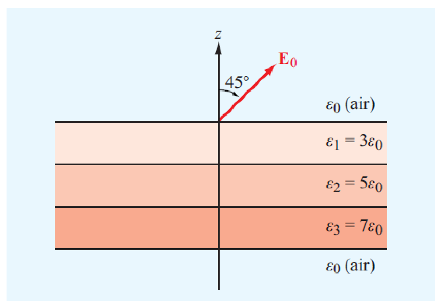
Figure P4.51 shows three planar dielectric slabs of equal thickness but with different dielectric constants. If E0 in air makes an angle of 45° with respect to the z axis, find the angle of E in each of the other layers.
Expert Solution & Answer
Want to see the full answer?
Check out a sample textbook solution
Students have asked these similar questions
1.
An electromagnetic device is shown below. The coil in the left side is connected to
a steady AC power source. The left coil generates a changing magnetic flux, which is =
1.5cos(120πt +л/6) T. Calculate the voltage vs generated across the right coil given the
number of turns of the right coil is 5 (You only need to calculate the magnitude).
Vp
For the closed loop system shown in figure, determine the following:
What is the open loop transfer function and feedback for thia system?
Determine the type of the open loop system.
Find the poles s1 and s2 of the open loop system.
If the input is a step function R(s)=1/s, find the step response c(t) of the open loop.
Chapter 4 Solutions
Fundamentals of Applied Electromagnetics (7th Edition)
Ch. 4.2 - What happens to Maxwells equations under static...Ch. 4.2 - How is the current density J related to the volume...Ch. 4.2 - Prob. 3CQCh. 4.2 - A square plate residing in the xy plane is...Ch. 4.2 - A thick spherical shell centered at the origin...Ch. 4.3 - When characterizing the electrical permittivity of...Ch. 4.3 - If the electric field is zero at a given point in...Ch. 4.3 - State the principle of linear superposition as it...Ch. 4.3 - Four charges of 10 C each are located in free...Ch. 4.3 - Two identical charges are located on the x axis at...
Ch. 4.3 - In a hydrogen atom the electron and proton are...Ch. 4.3 - An infinite sheet with uniform surface charge...Ch. 4.4 - Explain Gausss law. Under what circumstances is it...Ch. 4.4 - How should one choose a Gaussian surface?Ch. 4.4 - Two infinite lines, each carrying a uniform charge...Ch. 4.4 - A thin spherical shell of radius a carries a...Ch. 4.4 - A spherical volume of radius a contains a uniform...Ch. 4.5 - What is a conservative field?Ch. 4.5 - Why is the electric potential at a point in space...Ch. 4.5 - Prob. 11CQCh. 4.5 - Why is it usually easier to compute V for a given...Ch. 4.5 - Prob. 13CQCh. 4.5 - Determine the electric potential at the origin due...Ch. 4.5 - A spherical shell of radius a has a uniform...Ch. 4.6 - What are the electromagnetic constitutive...Ch. 4.6 - Prob. 15CQCh. 4.6 - What is the conductivity of a perfect dielectric?Ch. 4.6 - Prob. 17CQCh. 4.6 - Prob. 18CQCh. 4.6 - Determine the density of free electrons in...Ch. 4.6 - Prob. 13ECh. 4.6 - A 50 m long copper wire has a circular cross...Ch. 4.6 - Prob. 15ECh. 4.7 - What is a polar material? A nonpolar material?Ch. 4.7 - Prob. 20CQCh. 4.7 - What happens when dielectric breakdown occurs?Ch. 4.7 - Find E1 in Fig. 4-19 if E2=x2y3+z3(v/m),1=20,2=80,...Ch. 4.7 - Repeat Exercise 4.16 for a boundary with surface...Ch. 4.8 - What are the boundary conditions for the electric...Ch. 4.8 - Prob. 23CQCh. 4.9 - How is the capacitance of a two-conductor...Ch. 4.9 - What are fringing fields and when may they be...Ch. 4.10 - To bring a charge q from infinity to a given point...Ch. 4.10 - Prob. 27CQCh. 4.10 - The radii of the inner and outer conductors of a...Ch. 4.11 - What is the fundamental premise of the image...Ch. 4.11 - Given a charge distribution, what are the various...Ch. 4.11 - Use the result of Example 4-13 to find the surface...Ch. 4 - A cube 2 m on a side is located in the first...Ch. 4 - Prob. 2PCh. 4 - Find the total charge contained in a round-top...Ch. 4 - If the line charge density is given by l = 24y2...Ch. 4 - Find the total charge on a circular disk defined...Ch. 4 - If J = 4xz (A/m2), find the current I flowing...Ch. 4 - Prob. 7PCh. 4 - An electron beam shaped like a circular cylinder...Ch. 4 - Prob. 9PCh. 4 - A line of charge of uniform density occupies a...Ch. 4 - A square with sides of 2 m has a charge of 40 C at...Ch. 4 - Three point charges, each with q = 3 nC, are...Ch. 4 - Charge q1 = 6 C is located at (1 cm, 1 cm, 0) and...Ch. 4 - A line of charge with uniform density = 8 (C/m)...Ch. 4 - Prob. 15PCh. 4 - A line of charge with uniform density l extends...Ch. 4 - Repeat Example 4-5 for liie circular disk of...Ch. 4 - Multiple charges at different locations are said...Ch. 4 - Three infinite lines of charge, all parallel to...Ch. 4 - Prob. 20PCh. 4 - A horizontal strip lying in the xy plane is of...Ch. 4 - Prob. 22PCh. 4 - Prob. 23PCh. 4 - Charge Q1 is uniformly distributed over a thin...Ch. 4 - The electric flux density inside a dielectric...Ch. 4 - Prob. 26PCh. 4 - An infinitely long cylindrical shell extending...Ch. 4 - If the charge density increases linearly with...Ch. 4 - A spherical shell with outer radius b surrounds a...Ch. 4 - Prob. 30PCh. 4 - Prob. 31PCh. 4 - A circular ring of charge of radius a lies in the...Ch. 4 - Prob. 33PCh. 4 - Find the electric potential V at a location a...Ch. 4 - For the electric dipole shown in Fig. 4-13, d = 1...Ch. 4 - For each of the distributions of the electric...Ch. 4 - Two infinite lines of charge, both parallel to the...Ch. 4 - Given the electric field E=R18R2(V/m) find the...Ch. 4 - An infinitely long line of charge with uniform...Ch. 4 - The xy plane contains a uniform sheet of charge...Ch. 4 - A cylindrical bar of silicon has a radius of 4 mm...Ch. 4 - Repeat Problem 4.41 for a bar of germanium with e...Ch. 4 - A 100 m long conductor of uniform cross-section...Ch. 4 - Prob. 44PCh. 4 - Apply the result of Problem 4.44 to find the...Ch. 4 - A 2 103 mm thick square sheet of aluminum has 5 cm...Ch. 4 - A cylinder-shaped carbon resistor is 8 cm in...Ch. 4 - With reference to Fig. 4-19, find E1 if...Ch. 4 - An infinitely long cylinder of radius a is...Ch. 4 - If E=R150(V/m) at the surface of a 5-cm conducting...Ch. 4 - Figure P4.51 shows three planar dielectric slabs...Ch. 4 - Determine the force of attraction in a...Ch. 4 - Dielectric breakdown occurs in a material whenever...Ch. 4 - An electron with charge Qe = 1.61019 C and mass me...Ch. 4 - In a dielectric medium with r = 4, the electric...Ch. 4 - Prob. 56PCh. 4 - Prob. 57PCh. 4 - Prob. 58PCh. 4 - Prob. 59PCh. 4 - Prob. 60PCh. 4 - Prob. 61PCh. 4 - Conducting wires above a conducting plane carry...Ch. 4 - Prob. 63P
Knowledge Booster


Learn more about
Need a deep-dive on the concept behind this application? Look no further. Learn more about this topic, electrical-engineering and related others by exploring similar questions and additional content below.Similar questions
- not use ai please don'tarrow_forward2. A DC generator is shown below. This DC generator is driven by a prime mover and rotating in counterclockwise direction. The armature is connected with a load resistor. (i) Using cross (x) or dot (*) to indicate the current direction of each conductor in the armature. (ii) If we want to reverse the polarity of the generated armature voltage, what can we do to? rotation S load Narrow_forward6. The figures below show the equivalent circuit of a separately excited DC generator and the approximate relationship between the flux of main field and exciting current. The field current I can be regulated by the variable resistor Ry, and the battery voltage supplying power to the exciter is 12V. The armature resistance Ro is 20, and the load is 182. For the DC generator, we aim to keep the voltage across the load (RL) constant in different speed range conditions. In the beginning, the flux is 0.12 Wb, the DC generator speed is 1000 rpm, and the generated voltage E。 is 100 V. Calculate: (1) The current flowing through the load. (2) When the speed of generator changes to 1500 rpm, how should we adjust the exciting current Ix to ensure Ę is still 100 V. (Hint: E₁ = Zno/60) (3) When the speed of generator changes to 500 rpm, how should we adjust the exciting current Ix to ensure Eo is still 100 V. (Hint: Eo = Zno/60) Rf ww (Wb) 0.17 0.15 12 V 1x F ele 1 1 2 ell Eo Ro ww 9 w RL Ix (A)arrow_forward
- 7. For a shunt excited motor, the maximum allowable current is twice of the full-load current. The full-load current is 10 A. The equivalent circuit of this motor is also shown below. The rheostat can change the resistance by moving the slider (contact). The counter electromotive force (CEMF) for this motor is 100 V at 1000 rpm. The power supply E, is 200 V. In this case: (1) Calculate the minimum resistor value R at 0 rpm ensuing the motor is running within the safe range, and calculate the power consumed by the rheostat R. (2) Calculate the minimum effective resistor value R at 100 rpm ensuing the motor is running within the safe range, and calculate the power consumed by the rheostat R and the delivered mechanical power. (3) Calculate the minimum resistor value R at 500 rpm ensuing the motor is running within the safe range, and calculate the power consumed by the rheostat R the delivered mechanical power. shunt field R armature rheostat Es + Eoarrow_forward4. For a general DC generator, we aim to achieve constant output voltage at different rotating speeds. (1) List two factors influencing the output voltage for a given DC generator. (2) How does the change of the load (assuming the load is the current flowing though the resistor) will impact on the generated voltage for (a) separately excited DC generator, (b) Shunt DC generator, and (c) cumulative compound DC generator?arrow_forward3. A DC motor is shown below. The armature is supplied by an external battery, and the current flowing direction of each conduction is depicted in the figure. (i) Draw the Lorentz force direction applied on each conductor in the armature. (ii) In which direction will the motor spin? What can we do to reverse the spinning direction? S Narrow_forward
- 5. conditions. For a general DC motor, we aim to control the speed of the motor at different loading (1) List two factors influencing the motor speed for a given DC motor. (2) List three ways to stop a motor and comment on each method?arrow_forwardSolve by Pen and Paper not using chatgptarrow_forwardf. The figure below shows two stage RC coupled amplifier. If the input resistance Rin of each stage is 1kN. (B = 100). Determine its overall voltage gain. (5 marks) +15V ΣΚΩ kn 10kΩ 10ΚΩ output 35 ΚΩ 2ΚΩ 5kЛ 2ΚΩarrow_forward
arrow_back_ios
SEE MORE QUESTIONS
arrow_forward_ios
Recommended textbooks for you
 Introductory Circuit Analysis (13th Edition)Electrical EngineeringISBN:9780133923605Author:Robert L. BoylestadPublisher:PEARSON
 Delmar's Standard Textbook Of ElectricityElectrical EngineeringISBN:9781337900348Author:Stephen L. HermanPublisher:Cengage Learning
 Programmable Logic ControllersElectrical EngineeringISBN:9780073373843Author:Frank D. PetruzellaPublisher:McGraw-Hill Education
 Fundamentals of Electric CircuitsElectrical EngineeringISBN:9780078028229Author:Charles K Alexander, Matthew SadikuPublisher:McGraw-Hill Education
 Electric Circuits. (11th Edition)Electrical EngineeringISBN:9780134746968Author:James W. Nilsson, Susan RiedelPublisher:PEARSON
 Engineering ElectromagneticsElectrical EngineeringISBN:9780078028151Author:Hayt, William H. (william Hart), Jr, BUCK, John A.Publisher:Mcgraw-hill Education,
Introductory Circuit Analysis (13th Edition)
Electrical Engineering
ISBN:9780133923605
Author:Robert L. Boylestad
Publisher:PEARSON
Delmar's Standard Textbook Of Electricity
Electrical Engineering
ISBN:9781337900348
Author:Stephen L. Herman
Publisher:Cengage Learning
Programmable Logic Controllers
Electrical Engineering
ISBN:9780073373843
Author:Frank D. Petruzella
Publisher:McGraw-Hill Education
Fundamentals of Electric Circuits
Electrical Engineering
ISBN:9780078028229
Author:Charles K Alexander, Matthew Sadiku
Publisher:McGraw-Hill Education
Electric Circuits. (11th Edition)
Electrical Engineering
ISBN:9780134746968
Author:James W. Nilsson, Susan Riedel
Publisher:PEARSON
Engineering Electromagnetics
Electrical Engineering
ISBN:9780078028151
Author:Hayt, William H. (william Hart), Jr, BUCK, John A.
Publisher:Mcgraw-hill Education,
Demos: Dielectric breakdown; Author: Caltech's Feynman Lecture Hall;https://www.youtube.com/watch?v=2YrHh1ikefI;License: Standard Youtube License