
Concept explainers
The drawing of the hydraulic gradient line and the energy grade line of the given system.
Explanation of Solution
Given:
Formula used:
Calculation:
The given figure is shown below:
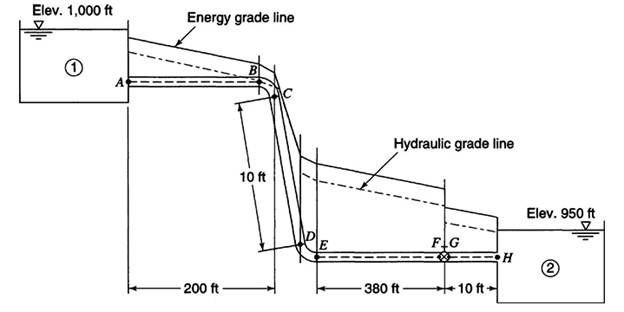
The flow between reservoir 1 and reservoir 2 is given by
The head loss is given by
The total minor head loss is given by
The relative roughness of pipe is given by
The value of the friction factor is 0.0165 from Moody’s diagram.
Now, substituting the value of the friction factor in the equation (1)
The discharge is given by
The velocity head is given by
The total head loss in the flow from A to B is given by
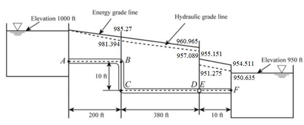
The hydraulic gradient line at B is given by
The energy gradient line at B is given by
Keep the hydraulic gradient line at point C the same as the hydraulic gradient line at point B.
The hydraulic gradient line at point C is given by
The energy gradient line at C is given by
The hydraulic gradient line at D is given by
The energy gradient line at D is given by
The hydraulic gradient line at E is given by
The energy gradient line at E is given by
The hydraulic gradient line at F is given by
The energy gradient line at F is given by
Want to see more full solutions like this?
Chapter 4 Solutions
WATER RESOURCES ENGINEERING (CL)


- 14.1 A beam of rectangular cross section is 125 mm wide and 200 mm deep. If the maximum bending moment is 28.5 kN⚫m, determine (a) the maximum tensile and compressive bending stress, and (b) the bending stress 25 mm from the top of the section. 14.2 A rectangular beam 50 mm wide and 100 mm deep is subjected to bending. What bending moment will cause a maximum bending stress of 137.9 MN/m² (MPa)? 14.3 Determine the bending moment in a rectangular beam 3 in. wide and 6 in. deep if the maximum bend- ing stress is 15,000 psi.arrow_forwardB3. For the Howe truss below, assume all members are pin connected and take P₁ = 5 kN and P₂ = 10 kN: a. Determine all member forces (16 pts). b. Use a section cut to verify your answers for members GF, GD, and CD (4 Pts) P₁ A H 500 8 0000 B 0000] 2 m m 2 m 3 m B E D marrow_forwardI need detailed help solving this exercise from homework of Engineering Mathematics II.I do not really understand how to do, please do it step by step, not that long but clear. Thank you!P.S.: Please do not use AI, thanks!arrow_forward
- I need detailed help solving this exercise from homework of Engineering Mathematics II.I do not really understand how to do, please do it step by step, not that long but clear. Thank you!P.S.: Please do not use AI, thanks!arrow_forwardI need detailed help solving this exercise from homework of Engineering Mathematics II.I do not really understand how to do, please do it step by step, not that long but clear. Thank you!P.S.: Please do not use AI, thanks!arrow_forwardI need detailed help solving this exercise from homework of Engineering Mathematics II.I do not really understand how to do, please do it step by step, not that long but clear. Thank you!P.S.: Please do not use AI, thanks!arrow_forward
- I need detailed help solving this exercise from homework of Engineering Mathematics II.I do not really understand how to do, please do it step by step, not that long but clear. Thank you!P.S.: Please do not use AI, thanks!arrow_forwardI need detailed help solving this exercise from homework of Engineering Mathematics II.I do not really understand how to do, please do it step by step, not that long but clear. Thank you!P.S.: Please do not use AI, thanks!arrow_forwardI need detailed help solving this exercise from homework of Engineering Mathematics II.I do not really understand how to do, please do it step by step, not that long but clear. Thank you!P.S.: Please do not use AI, thanks!arrow_forward
- I need detailed help solving this exercise from homework of Engineering Mathematics II.I do not really understand how to do, please do it step by step, not that long but clear. Thank you!P.S.: Please do not use AI, thanks!arrow_forwardB1.For the truss below, take P₁ = 4 kip and P₂ = 3 kip: a. Determine all member forces. Hint: first find zero-force members (16 pts). b. Use a section cut to verify your answers for members JI, BI, and BC (4 Pts) В 18 ft 6 ft H B 6 ft C 8 ft D p81 8 ft E 8 ft 6 ft F6ftarrow_forwardQ13: The line CD, C(xc, 6), D(6,yd), the point D is on the right of point C, the value of horizontal effect H(3,0) is on the right of point C, the vertical effect V(0, -2) right of H. the distance between projection of the points H, V is 5cm, Find: 1- The value of xc and yd. 2- The distance between projections of the points C, D. 3- The true length (T.L.) of CD. 4- The angles a and ẞ. 5- A point F in the middle of line CD, find F (xf, yf).arrow_forward
 Fundamentals of Geotechnical Engineering (MindTap...Civil EngineeringISBN:9781305635180Author:Braja M. Das, Nagaratnam SivakuganPublisher:Cengage Learning
 Principles of Geotechnical Engineering (MindTap C...Civil EngineeringISBN:9781305970939Author:Braja M. Das, Khaled SobhanPublisher:Cengage Learning
 Principles of Foundation Engineering (MindTap Cou...Civil EngineeringISBN:9781305081550Author:Braja M. DasPublisher:Cengage Learning
 Engineering Fundamentals: An Introduction to Engi...Civil EngineeringISBN:9781305084766Author:Saeed MoaveniPublisher:Cengage Learning
 Principles of Foundation Engineering (MindTap Cou...Civil EngineeringISBN:9781337705028Author:Braja M. Das, Nagaratnam SivakuganPublisher:Cengage Learning
 Solid Waste EngineeringCivil EngineeringISBN:9781305635203Author:Worrell, William A.Publisher:Cengage Learning,