Concept explainers
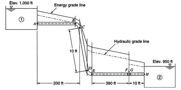
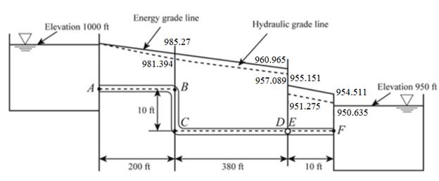
The drawing of the hydraulic gradient line and the energy grade line of the given system.
Explanation of Solution
Given:
Formula used:
Calculation:
The given figure is shown below:

The flow between reservoir 1 and reservoir 2 is given by
The head loss is given by
The total minor head loss is given by
The relative roughness of pipe is given by
The value of the friction factor is 0.0165 from Moody’s diagram.
Now, substituting the value of the friction factor in the equation (1)
The discharge is given by
The velocity head is given by
The total head loss in the flow from A to B is given by
The hydraulic gradient line at B is given by
The energy gradient line at B is given by
Keep the hydraulic gradient line at point C the same as the hydraulic gradient line at point B.
The hydraulic gradient line at point C is given by
The energy gradient line at C is given by
The hydraulic gradient line at D is given by
The energy gradient line at D is given by
The hydraulic gradient line at E is given by
The energy gradient line at E is given by
The hydraulic gradient line at F is given by
The energy gradient line at F is given by

Want to see more full solutions like this?
Chapter 4 Solutions
EBK WATER RESOURCES ENGINEERING
- . The average soil weights for a clay are the following: 2,050 pounds in Loose CY, 2,675pounds in Bank CY, and 2,835 pounds in Compacted CY What is the swell percentage for theclay?arrow_forwardA traffic count taken between 7:00 a.m. and 2:00 p.m. on a rural highway found the following hourly volumes. Time 7:00-8:00 a.m. Hourly volume 332 8:00-9:00 a.m. 311 9:00-10:00 a.m. 263 10:00-11:00 a.m. 273 11:00 a.m.-12:00 p.m. 289 12:00-1:00 p.m. 1:00-2:00 p.m. 286 265 If these data were collected on a Tuesday in February, estimate the AADT (in veh/day) on this section of highway. Assume that the expansion factors given in this table, this table, and this table apply. veh/dayarrow_forwardA project schedule has been updated. The activity placement of spread footing concretewas originally scheduled to begin as early as day 10. The activity duration is 4 days. The actualstart day was day 12. The original schedule had a calculated total float of 7 days for this activity.The recalculated total float for the activity, when updated, would bearrow_forward
- In preparation for a public hearing, an engineer needs to estimate the travel time savings for a proposed highway bypass of a small city in a rural area. The existing highway goes through the downtown area for 4.1 miles between the points where the bypass will connect. (a) If the engineer anticipates a standard deviation of 7 mi/h and would like a 95% confidence of estimating the mean speed within ±4 mi/h, how many runs should a travel time study include? (Enter the minimum number of runs that achieves a 95% confidence level.) runs (b) If the engineer measures an average speed of 34.9 mi/h through the town and the bypass is expected to operate at speeds of 65 mi/h over a distance of 6.2 miles, what is the expected travel time saving (in minutes) per vehicle? minutes Need Help? Read It Watch Itarrow_forwardfollow the instructions and make sure to right the complete solutionarrow_forwardDraw shear and moment diagrams for the attached image.arrow_forward
- I do not know how to approach this problemarrow_forwardConsider a pool of saturated water at atmospheric pressure. The base of the pool is made of thick polished copper square plate of length 1 m. To generate steam, exhaust gas is flowing underneath and parallel to the base plate with velocity 3 m/s and average temperate of 1090°C. The bottom surface the plate is at constant temperature of 110°. Use the properties of air for exhaust gas. a) Determine the boiling heat transfer rate. b) Determine the temperature of the top surface of the plate. Comment on the results. c) Examine the impact of your assumptions on your solutions. (what will change if any of the assumptions is not valid?)arrow_forward-The axial deflection pipe in inches. -The lateral deflection of the beam in inches -The total deflection of the beam like structure in inches ? all to 4 sig figs AI did not help. as i input what i get im not sure if its a rounding error or what.arrow_forward
 Fundamentals of Geotechnical Engineering (MindTap...Civil EngineeringISBN:9781305635180Author:Braja M. Das, Nagaratnam SivakuganPublisher:Cengage Learning
 Principles of Geotechnical Engineering (MindTap C...Civil EngineeringISBN:9781305970939Author:Braja M. Das, Khaled SobhanPublisher:Cengage Learning
 Principles of Foundation Engineering (MindTap Cou...Civil EngineeringISBN:9781305081550Author:Braja M. DasPublisher:Cengage Learning
 Engineering Fundamentals: An Introduction to Engi...Civil EngineeringISBN:9781305084766Author:Saeed MoaveniPublisher:Cengage Learning
 Principles of Foundation Engineering (MindTap Cou...Civil EngineeringISBN:9781337705028Author:Braja M. Das, Nagaratnam SivakuganPublisher:Cengage Learning
 Solid Waste EngineeringCivil EngineeringISBN:9781305635203Author:Worrell, William A.Publisher:Cengage Learning,


