
Concept explainers
Videos
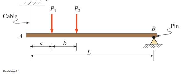
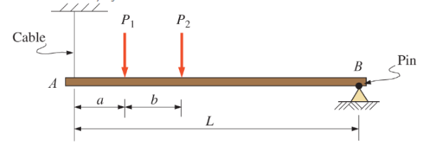
and 4.2 Sketch free-body diagram for the members shown.
The free body diagram of the given beam.
Explanation of Solution
Given Information:
Given member is
A free body diagram is a geometrical representation of the different forces acting on a body which are placed for the direct contact points of the body with the arrows showing their implemented direction thereby helping in evaluating the forces that act upon it.
We need to replace the loads with the forces that are there at every point of contact. The concentrated loads will be replaced by single reactions, the fixed cable will also be replaced by single reaction (don’t be confused if it is fixed, as fixed points have to be replaced by three reactions but in this case the beam isn’t directly fixed it is connected with the cable), the pinned by the two reactions and the self-weight with a single reaction.
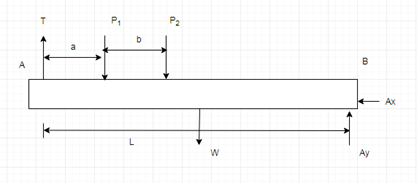
Free body diagram of the beam.
Want to see more full solutions like this?
Chapter 4 Solutions
Applied Statics and Strength of Materials (6th Edition)
Additional Engineering Textbook Solutions
Mechanics of Materials (10th Edition)
Starting Out with Python (4th Edition)
Starting Out with Java: From Control Structures through Objects (7th Edition) (What's New in Computer Science)
Vector Mechanics for Engineers: Statics
Web Development and Design Foundations with HTML5 (8th Edition)
Starting Out With Visual Basic (8th Edition)


- Please sovle this for me and please don't use aiarrow_forwardPlease sovle this for me and please don't use aiarrow_forward3. The cold-drawn AISI 1040 steel bar shown in the figure is subjected to a completely reversed axial load fluctuating between 28 kN in compression to 28 kN in tension. Estimate the fatigue factor of safety based on achieving infinite life (using Goodman line) and the yielding factor of safety. If infinite life is not predicted, estimate the number of cycles to failure. 25 mm + 6-mm D. 10 mmarrow_forward
- CORRECT AND DETAILED SOLUTION WITH FBD ONLY. I WILL UPVOTE 1. The truss shown is supported by hinge at A and cable at E.Given: H = 4m, S = 1.5 m, α = 75⁰, θ = 33⁰.Allowable tensile stress in cable = 64 MPa.Allowable compressive stress in all members = 120 MPaAllowable tensile stress in all members = 180 MPa1.Calculate the maximum permissible P, in kN, if the diameter of the cable is 20 mm.2.If P = 40 kN, calculate the required area (mm2) of member BC.3. If members have solid square section, with dimension 15 mm, calculate the maximum permissible P (kN) based on the allowable strength of member HI.ANSWERS: (1) 45.6 kN; (2) 83.71 mm2; (3) 171.76 kNarrow_forwardCORRECT AND DETAILED SOLUTION WITH FBD ONLY. I WILL UPVOTE 2: A wire 4 meters long is stretched horizontally between points 4 meters apart. The wire is 25 mm2 in cross-section with a modulus of elasticity of 200 GPa. A load W placed at the center of the wire produces a sag Δ.1.Calculate the tension (N) in the wire if sag Δ = 30 mm.2.Calculate the magnitude of W, in N, if sag Δ = 54.3 mm.3. If W is 60 N, what is the sag (in mm)?ANSWERS: (1) 562 N, (2) 100 N, (3) 45.8 Narrow_forwardCORRECT AND DETAILED SOLUTION WITH FBD ONLY. I WILL UPVOTE 4 : A cable and pulley system at D is used to bring a 230-kg pole (ACB) to a vertical position as shown. The cable has tensile force T and is attached at C. The length of the pole is 6.0 m, the outer diameter is d = 140 mm, and the wall thickness t = 12 mm. The pole pivots about a pin at A. The allowable shear stress in the pin is 60 MPa and the allowable bearing stress is 90 MPa. The diameter of the cable is 8 mm.1.Find the minimum diameter (mm) of the pin at A to support the weight of the pole in the position shown.2.Calculate the elongation (mm) of the cable CD.3.Calculate the vertical displacement of point C, in mm.ANSWERS: (1) 6 mm, (2) 1.186 mm, (3) 1.337 mm--arrow_forward
- 1. Derive an expression for H(w) filter or bandpass/reject filter. = for the circuit below. Qualitatively determine if it's a high/lowpass L ell R ww Voarrow_forward2. Obtain the transfer function, H(w) = 0 for the circuit below for R₁ = 1 kQ2, R2 = 10 kQ, and Vi C = 1 μF. What role, if any, does the capacitor play? Explain. R₁ R2 + C + Voarrow_forwardCORRECT AND DETAILED SOLUTION WITH FBD ONLY. I WILL UPVOTE 3 (15 points): A 12-meter-long precast pile segment is to be lifted from a trailer down to the ground and then set in place prior to driving by a crane.1. If two slings are to be used in lifting the pile to the ground, at what distance from the ends must the slings be placed for minimum bending due to its own weight?2. At what distance from the ends must the slings be placed for minimum shear due to its own weight?3. Using one sling to set the pile in a vertical position before driving at what distance from one end must the sling be placed for minimum bending due to its own weight?ANSWERS: (1) 2.48 m, (2) 3.00 m, (3) 3.51 marrow_forward
 Elements Of ElectromagneticsMechanical EngineeringISBN:9780190698614Author:Sadiku, Matthew N. O.Publisher:Oxford University Press
 Mechanics of Materials (10th Edition)Mechanical EngineeringISBN:9780134319650Author:Russell C. HibbelerPublisher:PEARSON
 Thermodynamics: An Engineering ApproachMechanical EngineeringISBN:9781259822674Author:Yunus A. Cengel Dr., Michael A. BolesPublisher:McGraw-Hill Education
 Control Systems EngineeringMechanical EngineeringISBN:9781118170519Author:Norman S. NisePublisher:WILEY
 Mechanics of Materials (MindTap Course List)Mechanical EngineeringISBN:9781337093347Author:Barry J. Goodno, James M. GerePublisher:Cengage Learning
 Engineering Mechanics: StaticsMechanical EngineeringISBN:9781118807330Author:James L. Meriam, L. G. Kraige, J. N. BoltonPublisher:WILEY