
Videos
The properties of seven different clayey soils are shown below (Skempton and Northey, 1952). Investigate the relationship between the strength and plasticity characteristics by performing the following tasks:
a. Estimate the plasticity index for each soil using Skempton’s definition of activity [Eq. (4.28)].
b. Estimate the probable mineral composition of the clay soils based on PI and A (use Table 4.3)
c. Sensitivity (St) refers to the loss of strength when the soil is remolded or disturbed. It is defined as the ratio of the undisturbed strength (τf-undisturbed) to the remolded strength (τf-remolded)) at the same moisture content [Eq. (12.49)]. From the given data, estimate τf-remolded for the clay soils.
d. Plot the variations of undisturbed and remolded shear strengths with the activity, A, and explain the observed behavior.
(a)
Find the plasticity index for each soil using Skempton’s definition of activity.
Explanation of Solution
Determine the plasticity index of the Beauharnais soil using the relation.
Here, A is an activity.
Substitute 0.52 for A and 79 for % of clay–size fraction, by weight.
Similarly, calculate the plasticity index for the remaining soils.
Determine the remolded shear strength of the Beauharnais soil using the relation.
Here,
Substitute
Similarly, calculate the remolded shear strength of the remaining soils.
Summarize the calculated values of plasticity index and the remolded shear strength as in Table 1.
| Soil | % Clay fraction | Activity A | Plasticity Index |
| Beauharnois | 79 | 0.52 | 41.08 |
| Detroit I | 36 | 0.36 | 12.96 |
| Horten | 40 | 0.42 | 16.80 |
| Gosport | 55 | 0.89 | 48.95 |
| Mexico City | 90 | 4.5 | 405 |
| Shell haven | 41 | 1.33 | 54.53 |
| St.Thuribe | 36 | 0.33 | 11.88 |
(b)
Find the probable mineral composition of the clay soils based on PI and A.
Explanation of Solution
Determine the probable mineral composition of the clay soils based on PI and A.
Refer Table 4.3, “Typical values of liquid limit, plastic limit, and activity of some clay minerals” in the textbook.
Take the mineral composition of the Beauharnois soil as Illite for the activity value of 0.52 and the plasticity index value of 41.08.
Therefore, the mineral composition of Beauharnois soil is Illite.
Similarly, calculate the probable mineral composition of the remaining soils.
Summarize the calculated values of mineral composition as in Table (2).
| Soil | Activity A | Plasticity Index | Mineral composition |
| Beauharnois | 0.52 | 41.08 | Illite |
| Detroit I | 0.36 | 12.96 | Kaolinite |
| Horten | 0.42 | 16.80 | Kaolinite |
| Gosport | 0.89 | 48.95 | Illite |
| Mexico City | 4.5 | 405 | Montmorillonite |
| Shell haven | 1.33 | 54.53 | Montmorillonite |
| St.Thuribe | 0.33 | 11.88 | Kaolinite |
(c)
Find the remoulded shear strength of the clay soil.
Explanation of Solution
Determine the remoulded shear strength of the Beauharnais soil using the relation.
Here,
Substitute
Similarly, calculate the remolded shear strength of the remaining soils.
Summarize the calculated values of remolded shear strength as in Table 3.
| Soil | Activity A | Undisturbed Shear strength | Sensitivity |
Remoulded Shear strength |
| Beauharnois | 0.52 | 18 | 14 | 1.3 |
| Detroit I | 0.36 | 17 | 2.5 | 6.8 |
| Horten | 0.42 | 41 | 17 | 2.4 |
| Gosport | 0.89 | 29 | 2.2 | 13.2 |
| Mexico City | 4.5 | 46 | 5.3 | 8.7 |
| Shell haven | 1.33 | 36 | 7.6 | 4.7 |
| St.Thuribe | 0.33 | 38 | 150 | 0.3 |
(d)
Plot the variations of undisturbed and remolded shear strengths with the activity A.
Explanation of Solution
Refer Table 3.
Plot the graph between the undisturbed, remolded shear strengths with the activity A as in Figure 1.
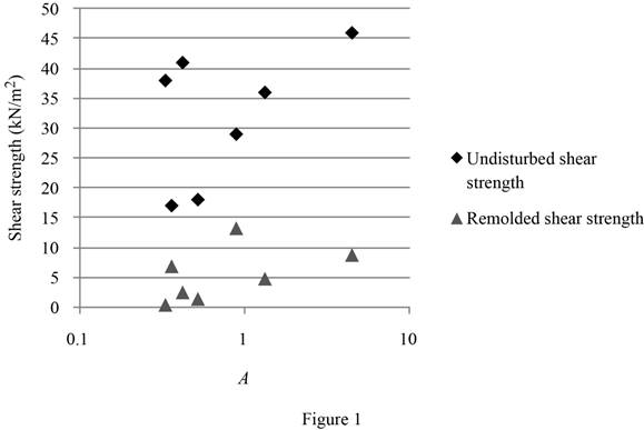
The shear strength of the clay obtains from two components, one is cohesion, which is the cementing force between particles, and second one is frictional resistance, which is mainly due to the particle movement of one particle over another. The cohesion contribution is greater to the shear strength, when the clay activity is greater. Although no reliable correlation can be developed from Figure 1, both the undisturbed and remolded shear strengths certainly show increasing trends as the activity increases.
Want to see more full solutions like this?
Chapter 4 Solutions
PRIN.OF GEOTECHNICAL...-MINDTAP(2 SEM)


- A frame is loaded by a force Q = 280 N and supported by pins at points B and C as shown below. The distances are given as a = 0.4 m, b = 0.8 m, c = 0.6 m, d = 2.6 m, and e = 1.5 m. b C с d a A B Q D e Determine the reactions at joints B and C. Report all answers in units of N with 2 decimal places of precision. Positive signs indicate that a force component acts in the positive axis direction (i.e. up or right), while a negative sign should be used to indicate a force component acting in a negative axis direction (i.e. down or left). The x-component of the reaction force at joint B, Bx = NⓇ The y-component of the reaction force at joint B, By = NⓇ NⓇ The x-component of the reaction force at joint C, Cx = The y-component of the reaction force at joint C, C₁ = N Numberarrow_forwardD Ø A vertical pole supports a horizontal cable CD and is supported by a ball-and-socket joint at A as shown in the figure below. Cable CD is parallel to the x-z plane (which implies that a vector from C to D has no y-component) and is oriented at an angle = 20° from the x-y plane. The distances are given as h = 10 m, b = 6 m, a = 9 m, and d = 4 m. y a b B The magnitude of the tension force in cable BE, TBE = KN ® F® Determine the following forces for this system if there is a 15 kN tension carried in cable CD. Report all answers in units of kN with 1 decimal place of precision. For the components of the reaction at A, be sure to use a positive or negative sign to indicate the direction of the force (negative signs if the force acts in the negative axial direction). The magnitude of the tension force in cable BF, TBF = KN The x-component of the reaction at joint A, Ax The y-component of the reaction at joint A, A, ®®® The z-component of the reaction at joint A, Az = = KN = KN KNarrow_forward(10 points) Problem 4. Suppose only through traffic is allowed on an intersection approach, and traffic arrive at a constant rate of 400 veh/h. Their effective green time is set to 15 seconds. Cycle length is 60 seconds. Estimate the average delay for that approach. Use a saturation flow rate of 1750 veh/h; D/D/1 queuing. Centenniam ad) of gy dov yasm wof ni emilarrow_forward
- A vertical pole supports a horizontal cable CD and is supported by a ball-and-socket joint at A as shown in the figure below. Cable CD is parallel to the x-z plane (which implies that a vector from C to D has no y-component) and is oriented at an angle = 20° from the x-y plane. The distances are given as h = 10 m, b = 6 m, a = 9 m, and d = 4 m. D C a B Determine the following forces for this system if there is a 15 kN tension carried in cable CD. Report all answers in units of kN with 1 decimal place of precision. For the components of the reaction at A, be sure to use a positive or negative sign to indicate the direction of the force (negative signs if the force acts in the negative axial direction). The magnitude of the tension force in cable BE, TBE = KN ☑ The magnitude of the tension force in cable BF, TBF = KN The x-component of the reaction at joint A, Ax = ☑ KN The y-component of the reaction at joint A, A, = KN The z-component of the reaction at joint A, Az = KN ☑arrow_forwardA vertical pole supports a horizontal cable CD and is supported by a ball-and-socket joint at A as shown in the figure below. Cable CD is parallel to the x-z plane (which implies that a vector from C to D has no y-component) and is oriented at an angle : = 20° from the x-y plane. The distances are given as h = 10 m, b = 6 m, a = 9 m, and d = 4 m. D C a B x Determine the following forces for this system if there is a 15 kN tension carried in cable CD. Report all answers in units of kN with 1 decimal place of precision. For the components of the reaction at A, be sure to use a positive or negative sign to indicate the direction of the force (negative signs if the force acts in the negative axial direction). The magnitude of the tension force in cable BE, TBE = 4.1 KN The magnitude of the tension force in cable BF, TBF = 41.1 KN The x-component of the reaction at joint A, Ax = 309.C KN ®®®® F The y-component of the reaction at joint A, Ay = -216. KN The z-component of the reaction at…arrow_forwardA small barrel weighing 400 N is lifted by a pair of tongs as shown. Knowing that h = 200 mm, L₁ = 400 mm, L2 = 120 mm and L3 = 200 mm, determine the magnitude of the forces exerted on member ABD of this machine structure. C L2 A P L1 L3 B D Report your answers in units of N with 2 decimal places of precision. N. The magnitude of the force acting at joint B = The magnitude of the force acting at joint D = N.arrow_forward
- A frame is loaded by a force Q = 280 N and supported by pins at points B and C as shown below. The distances are given as a = 0.4 m, b = 0.8 m, c = 0.6 m, d = 2.6 m, and e = 1.5 m. b C C d 11041 A B Q C D e Determine the reactions at joints B and C. Report all answers in units of N with 2 decimal places of precision. Positive signs indicate that a force component acts in the positive axis direction (i.e. up or right), while a negative sign should be used to indicate a force component acting in a negative axis direction (i.e. down or left). The x-component of the reaction force at joint B, Bx = N The y-component of the reaction force at joint B, By = N The x-component of the reaction force at joint C, Cx = N The y-component of the reaction force at joint C, Cy == Narrow_forwardI need help drawing the digram.arrow_forward8 m B 4 m Figure Q1 120 kN 4 marrow_forward
- ** Please do not put the n value as 0.024 it is incorrect. Also, please remember to identify the channel type.arrow_forward7. A rectangular, unfinished concrete channel of 38-ft width is laid on a slope of 8 ft/mi. Determine the flow depth and Froude number of the flow if the flowrate is 400 ft³/s.arrow_forward***Please MAKE SURE to include all parts that I have shown in the 8 steps here and follow them but also show work for the entire problem. Those are all correct I just need the entire worked out problem with all of the work.arrow_forward
 Principles of Geotechnical Engineering (MindTap C...Civil EngineeringISBN:9781305970939Author:Braja M. Das, Khaled SobhanPublisher:Cengage Learning
 Principles of Foundation Engineering (MindTap Cou...Civil EngineeringISBN:9781337705028Author:Braja M. Das, Nagaratnam SivakuganPublisher:Cengage Learning