
Matlab
6th Edition
ISBN: 9781119299257
Author: Amos Gilat
Publisher: WILEY CONS
expand_more
expand_more
format_list_bulleted
Videos
Textbook Question
Chapter 4, Problem 3P
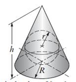
Write a MATLAB program that determines the radius, R, of the largest sphere that can be inscribed inside a cone with base radius R and height h. For input the program asks the user to enter values for R and h. The program then calculates r rounded to the nearest tenth.
For output the program displays the message: “The radius of the largest sphere that can be inscribed inside a cone with a base radius of XX in. and height of XX in., is: XX in.” where XX are the corresponding numerical values. Use the program to determine r for a cone with R = 8 in. and h =22 in.
Expert Solution & Answer
Want to see the full answer?
Check out a sample textbook solution
Students have asked these similar questions
electric plants.
Prepare the load schedule
electric plants
Draw the column diagram. Calculate the voltage drop. by hand writing
electric plants.
Draw the lighting, socket, telephone, TV, and doorbell installations on the given single-story project with an architectural plan by hand writing
Chapter 4 Solutions
Matlab
Ch. 4 - Prob. 1PCh. 4 - The altitude, h, as a function of air pressure can...Ch. 4 - Write a MATLAB program that determines the radius,...Ch. 4 - Radioactive decay can be modeled by the equation...Ch. 4 - A fuel tank is made of a half cylinder (r =14 in.)...Ch. 4 - A 300-lb garage door is being opened by pulling on...Ch. 4 - Write a MATLAB program in a script file that...Ch. 4 - The reduction of the amount of medication in the...Ch. 4 - The value of a saving account, V, after t years is...Ch. 4 - The electricity supply cables of the three houses...
Ch. 4 - Early explorers often estimated altitude by...Ch. 4 - An isosceles triangle sign is designed to have a...Ch. 4 - The angle ? at which a viewer sees the picture on...Ch. 4 - A 12-ft (144-in.) wire is cut into eight pieces...Ch. 4 - A person at point A spots a child in trouble at...Ch. 4 - The maximum stress smax at the edge of a hole...Ch. 4 - The airplane shown is flying at a constant speed...Ch. 4 - The intrinsic electrical conductivity a of a...Ch. 4 - The pressure drop ?p in pascals (Pa) for a fluid...Ch. 4 - The net heat exchange by radiation from plate 1...Ch. 4 - The equation of a circle in a plane with radius R...Ch. 4 - A truss is a structure made of members joined at...Ch. 4 - A truss is a Structure made of members joined at...Ch. 4 - The graph of the function f(x)=ax3+bx2+cx+d passes...Ch. 4 - The graph of the function f(x)=ax4+bx3+cx2+dx+e...Ch. 4 - The surface of many airfoils can be described with...Ch. 4 - During a golf match, a certain number of points...Ch. 4 - The dissolution of copper sulfide in aqueous...Ch. 4 - The heat index HI, calculated from the air...Ch. 4 - The stress intensity factor K at a crack is given...
Knowledge Booster


Learn more about
Need a deep-dive on the concept behind this application? Look no further. Learn more about this topic, statistics and related others by exploring similar questions and additional content below.Similar questions
- A circularly polarized wave, traveling in the +z-direction, is received by an elliptically polarized antenna whose reception characteristics near the main lobe are given approx- imately by E„ = [2â, + jâ‚]ƒ(r. 8, 4) Find the polarization loss factor PLF (dimensionless and in dB) when the incident wave is (a) right-hand (CW) An elliptically polarized wave traveling in the negative z-direction is received by a circularly polarized antenna. The vector describing the polarization of the incident wave is given by Ei= 2ax + jay.Find the polarization loss factor PLF (dimensionless and in dB) when the wave that would be transmitted by the antenna is (a) right-hand CParrow_forwardjX(1)=j0.2p.u. jXa(2)=j0.15p.u. jxa(0)=0.15 p.u. V₁=1/0°p.u. V₂=1/0° p.u. 1 jXr(1) = j0.15 p.11. jXT(2) = j0.15 p.u. jXr(0) = j0.15 p.u. V3=1/0° p.u. А V4=1/0° p.u. 2 jX1(1)=j0.12 p.u. 3 jX2(1)=j0.15 p.u. 4 jX1(2)=0.12 p.11. JX1(0)=0.3 p.u. jX/2(2)=j0.15 p.11. X2(0)=/0.25 p.1. Figure 1. Circuit for Q3 b).arrow_forwardcan you show me full workings for this problem. the solution is - v0 = 10i2 = 2.941 volts, i0 = i1 – i2 = (5/3)i2 = 490.2mA.arrow_forward
- Q4. a) Consider a transmission line modelled as a four-terminal network with an unknown configuration. You are provided with the following measured parameters at the operating frequency: Open-circuit voltage ratio: 0.9521° • Short-circuit impedance: 40+j80 • Open-circuit admittance: -j2 × 10-4 S Use the four terminal equations and the provided measurements to mathematically derive the A, B, C, and D parameters of the network and explain their physical significance. Show your work and formulas used in the derivation.arrow_forwardQ1. Consider a single-phase step-down transformer with primary and secondary turns of 600 and 100 respectively and a primary voltage of 11 kV. (i) An open circuit test was conducted on the transformer and the primary current was measured as: I₁ = 2.20 A Use these results to calculate the magnetising reactance in the equivalent circuit (X) given that Rm, representing the core loss, has a value of 21 km. (ii) The remaining equivalent circuit parameters are as follows: R₁ = 40, X₁ = 25 N, R₂ = 0.4 N, X₂ = 0.3 N Draw the complete simplified equivalent circuit, by referring series components on the primary side to the secondary, giving all component values. (iii) The transformer is connected, on its secondary side, to a load of 10 at a power factor of 1. Calculate the voltage across the load. (iv) Calculate the efficiency of the transformer when operating at the load given in part (iii).arrow_forwardb) A 132 kV supply feeds a line of reactance 15 which is connected to a 100 MVA, 132/33 kV transformer of 0.08 p.u. reactance as shown in the Figure 2. The transformer feeds a 33 kV line of reactance 8 Q, which, in turn, is connected to a 75 MVA, 33/11 KV transformer of 0.12 p.u. reactance. The transformer supplies an 11 KV substation from which a local 11 kV feeder of 4 Q reactance is supplied. T1 T2 132 kV 33 kV 11 kV Fault X CB Relay Figure 2. Network for Q4 b). (i) Given the system base of 100 MVA, compute the total equivalent reactance of the radial circuit in per unit (p.u.). (ii) Determine the three-phase fault current at the load end of the 11 kV feeder, assuming a fault impedance of 0.05 Q. Calculate the fault current in Amperes. (iii) The 11 kV feeder connects to a protective overcurrent relay via 200/5 A current transformers. This relay has a standard normally inverse IDMT characteristic, with a setting current of 3 A and a time multiplier setting of 0.4. Calculate the…arrow_forward
- Q2. a) Two three-phase transformers, designated A and B, have the following secondary equivalent circuit parameters per phase: R₁ = 0.002 Q, XA = 0.03 Q, RB = 0.004 Q, X = 0.012 Q Transformer A is 250 kVA and transformer B is 450 kVA. Calculate how they share a load of 650 KVA when connected in parallel (assume the voltage ratios are equal) b) A step-up transformer is being specified for the beginning of a 3-phase, 4 wire high voltage transmission line. Discuss your recommendation for the configuration of the transformer connections on both the primary and secondary side of the transformer. c) Define power system protection and describe its fundamental purpose. Discuss the following key concepts including discrimination, stability, speed of operation, sensitivity, and reliability in the context of the power system protection components and schemes.arrow_forwardQ3. a) Given the unsymmetrical phasors for a three-phase system, they can be represented in terms of their symmetrical components as follows: [Fa] [1 1 Fb = 1 a² [Fc. 11[Fao] a Fai 1 a a2F a2- where F stands for any three-phase quantity. Conversely, the sequence components can be derived from the unsymmetrical phasors as: [11 1] [Fal Faol Fa1 = 1 a a² F 1 a² a a2. Given the unbalanced three-phase voltages: V₁ = 120/10° V, V₂ = 200/110° V, V = 240/200° V Calculate in polar form the sequence components of the voltage.arrow_forwardComplete the table of values for this circuit:arrow_forward
- *P2.58. Solve for the node voltages shown in Figure P2.58. - 10 Ω w + 10 Ω 15 Ω w w '+' 5 Ω 20x 1 A Figure P2.58 w V2 502 12Aarrow_forwardAn 18.65 kW, 4-pole, 50 Hz, 3-phase induction motor has friction and windage losses of 2.5% of the output. The full-load slip is 4%. Find for full-load (i) the rotor cu loss (ii) the rotor input power (iii) the output torque.arrow_forwardQ1: Consider the finite state machine logic implementation in Fig. shown below: a. b. Construct the state diagram. Repeat the circuit design using j-k flip flop. C'lk A D 10 Clk Q D 32 Cik O 31 Please solve the question on a sheet of paper by hand and explain everything related to the question step by step.arrow_forward
arrow_back_ios
SEE MORE QUESTIONS
arrow_forward_ios
Recommended textbooks for you
 Power System Analysis and Design (MindTap Course ...Electrical EngineeringISBN:9781305632134Author:J. Duncan Glover, Thomas Overbye, Mulukutla S. SarmaPublisher:Cengage Learning
Power System Analysis and Design (MindTap Course ...
Electrical Engineering
ISBN:9781305632134
Author:J. Duncan Glover, Thomas Overbye, Mulukutla S. Sarma
Publisher:Cengage Learning
Surface Area Of A Sphere | Geometry | Math | Letstute; Author: Let'stute;https://www.youtube.com/watch?v=T_DBkFnr4NM;License: Standard YouTube License, CC-BY