Statics and Mechanics of Materials
2nd Edition
ISBN: 9780073398167
Author: Ferdinand P. Beer, E. Russell Johnston Jr., John T. DeWolf, David Mazurek
Publisher: McGraw-Hill Education
expand_more
expand_more
format_list_bulleted
Videos
Textbook Question
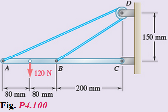
Chapter 4, Problem 100RP
Neglecting friction and the radius of the pulley, determine (a) the tension in cable ADB, (b) the reaction at C.
Expert Solution & Answer
Want to see the full answer?
Check out a sample textbook solution
Students have asked these similar questions
The gears shown in the figure have a diametral pitch of 2 teeth per inch and a 20° pressure angle.
The pinion rotates at 1800 rev/min clockwise and transmits 200 hp through the idler pair to gear
5 on shaft c. What forces do gears 3 and 4 transmit to the idler shaft?
TS
I
y
18T
32T
This
a
12
x
18T
C
48T
5
Question 1. Draw 3 teeth for the following pinion and gear respectively. The teeth
should be drawn near the pressure line so that the teeth from the pinion should
mesh those of the gear. Drawing scale (1:1). Either a precise hand drawing or
CAD drawing is acceptable. Draw all the trajectories of the involute lines and the
circles.
Specification: 18tooth pinion and 30tooth gear. Diameter pitch=P=6 teeth /inch.
Pressure angle:20°, 1/P for addendum (a) and 1.25/P for dedendum (b). For fillet,
c=b-a.
5. The figure shows a gear train. There is no friction at the bearings except for the gear tooth forces.
The material of the milled gears is steel having a Brinell hardness of 170. The input shaft speed (n2)
is 800 rpm. The face width and the contact angle for all gears are 1 in and 20° respectively. In this
gear set, the endurance limit (Se) is 15 kpsi and nd (design factor) is 2.
(a) Find the revolution speed of gear 5.
(b) Determine whether each gear satisfies the design factor of 2.0 for bending fatigue.
(c) Determine whether each gear satisfies the design factor of 2.0 for surface fatigue (contact stress).
(d) According to the computation results of the questions (b) and (c), explain the possible failure
mechanisms for each gear.
N4=28
800rpm
N₁=43
N5=34
N₂=14
P(diameteral pitch)=8 for all gears
Coupled to 2.5hp motor
Chapter 4 Solutions
Statics and Mechanics of Materials
Ch. 4.1 - For the beam and loading shown, determine (a) the...Ch. 4.1 - A 3200-lb forklift truck is used to lift a 1700-lb...Ch. 4.1 - A gardener uses a wheelbarrow to transport a 250-N...Ch. 4.1 - A load of lumber of weight W=25 kN is being raised...Ch. 4.1 - Three loads are applied as shown to a light beam...Ch. 4.1 - Three loads are applied as shown to a light beam...Ch. 4.1 - For the beam and loading shown, determine the...Ch. 4.1 - Prob. 8PCh. 4.1 - Prob. 9PCh. 4.1 - The lever BCD is hinged at C and attached to a...
Ch. 4.1 - The lever BCD is hinged at C and attached to a...Ch. 4.1 - A lever AB is hinged at C and attached to a...Ch. 4.1 - Determine the reactions at A and B when...Ch. 4.1 - Prob. 14PCh. 4.1 - Prob. 15PCh. 4.1 - Prob. 16PCh. 4.1 - A light bar AD is suspended from a cable BE and...Ch. 4.1 - Prob. 18PCh. 4.1 - Prob. 19PCh. 4.1 - Two slots have been cut in plate DEF, and the...Ch. 4.1 - A 6-m telephone pole weighing 1600 N is used to...Ch. 4.1 - Prob. 22PCh. 4.1 - For the and crate of Prob. 4.22 and assuming that...Ch. 4.1 - A tension of 20 N is maintained in a tape as it...Ch. 4.1 - The bracket ABC can be supported in the eight...Ch. 4.1 - Eight identical 500750-mm rectangular plates, each...Ch. 4.2 - Determine the reactions at B and C when a=30mm.Ch. 4.2 - Prob. 28PCh. 4.2 - A 12-ft wooden beam weighing 80 lb is supported by...Ch. 4.2 - Prob. 30PCh. 4.2 - One end of rod AB rests in the comer A and the...Ch. 4.2 - Using the method of Sec. 4.2B, solve Prob. 4.12.Ch. 4.2 - Prob. 33PCh. 4.2 - A 40-lb roller of 8-in. diameter, which is to be...Ch. 4.2 - Member ABC is supported by a pin and bracket at B...Ch. 4.2 - Prob. 36PCh. 4.2 - Prob. 37PCh. 4.2 - For the frame and loading shown, detennine the...Ch. 4.2 - For the boom and loading shown, determine (a) the...Ch. 4.2 - A slender rod BC of length L and weight W is held...Ch. 4.2 - Prob. 41PCh. 4.2 - Prob. 42PCh. 4.2 - Prob. 43PCh. 4.2 - Prob. 44PCh. 4.2 - Solve Prob. 4.44, assuming that the 170-N force...Ch. 4.2 - Prob. 46PCh. 4.2 - Prob. 47PCh. 4.2 - Prob. 48PCh. 4.2 - Prob. 49PCh. 4.2 - Prob. 50PCh. 4.3 - Two transmission belts pass over a double-sheaved...Ch. 4.3 - Solve Prob. 4.51, assuming that the pulley rotates...Ch. 4.3 - A 48-ft sheet of plywood weighing 40 lb has been...Ch. 4.3 - Prob. 54PCh. 4.3 - Prob. 55PCh. 4.3 - Prob. 56PCh. 4.3 - Prob. 57PCh. 4.3 - Prob. 58PCh. 4.3 - Prob. 59PCh. 4.3 - Prob. 60PCh. 4.3 - A 48-in. boom is held by a ball-and-socket joint...Ch. 4.3 - Prob. 62PCh. 4.3 - The 6-m pole ABC is acted upon by a 455-N force as...Ch. 4.3 - A 600-lb crate hangs from a cable that passes over...Ch. 4.3 - The horizontal platform ABCD weighs 60 lb and...Ch. 4.3 - Prob. 66PCh. 4.3 - Prob. 67PCh. 4.3 - Prob. 68PCh. 4.3 - A 10-kg storm window measuring 9001500 mm is held...Ch. 4.3 - Prob. 70PCh. 4.3 - Prob. 71PCh. 4.3 - Solve Prob. 4.69, assuming that the hinge at A has...Ch. 4.3 - Prob. 73PCh. 4.3 - Three rods are welded together to form a corner...Ch. 4.4 - Determine whether the block shown is in...Ch. 4.4 - Prob. 76PCh. 4.4 - Determine whether the block shown is in...Ch. 4.4 - Prob. 78PCh. 4.4 - Prob. 79PCh. 4.4 - Prob. 80PCh. 4.4 - Prob. 81PCh. 4.4 - Prob. 82PCh. 4.4 - Prob. 83PCh. 4.4 - Knowing that P=100N, determine the range of values...Ch. 4.4 - A 120-lb cabinet is mounted on casters that can be...Ch. 4.4 - Prob. 86PCh. 4.4 - A 40-kg packing crate must be moved to the left...Ch. 4.4 - A 40-kg packing crate is pulled by a rope as...Ch. 4.4 - Prob. 89PCh. 4.4 - Prob. 90PCh. 4.4 - Prob. 91PCh. 4.4 - Prob. 92PCh. 4.4 - Prob. 93PCh. 4.4 - Prob. 94PCh. 4.4 - Prob. 95PCh. 4.4 - Prob. 96PCh. 4.4 - The cylinder shown is of weight W and radius r,...Ch. 4.4 - Prob. 98PCh. 4 - A T-shaped bracket supports the four loads shown....Ch. 4 - Neglecting friction and the radius of the pulley,...Ch. 4 - Member ABC is supported by a pin and bracket at B...Ch. 4 - Prob. 102RPCh. 4 - Prob. 103RPCh. 4 - Prob. 104RPCh. 4 - Prob. 105RPCh. 4 - Prob. 106RPCh. 4 - Prob. 107RPCh. 4 - Prob. 108RPCh. 4 - Prob. 109RPCh. 4 - Two 10-lb blocks A and B are connected by a...
Knowledge Booster


Learn more about
Need a deep-dive on the concept behind this application? Look no further. Learn more about this topic, mechanical-engineering and related others by exploring similar questions and additional content below.Similar questions
- 1. The rotating steel shaft is simply supported by bearings at points of B and C, and is driven by a spur gear at D, which has a 6-in pitch diameter. The force F from the drive gear acts at a pressure angle of 20°. The shaft transmits a torque to point A of TA =3000 lbĘ in. The shaft is machined from steel with Sy=60kpsi and Sut=80 kpsi. (1) Draw a shear force diagram and a bending moment diagram by F. According to your analysis, where is the point of interest to evaluate the safety factor among A, B, C, and D? Describe the reason. (Hint: To find F, the torque Tд is generated by the tangential force of F (i.e. Ftangential-Fcos20°) When n=2.5, K=1.8, and K₁ =1.3, determine the diameter of the shaft based on (2) static analysis using DE theory (note that fatigue stress concentration factors need to be used for this question because the loading condition is fatigue) and (3) a fatigue analysis using modified Goodman. Note) A standard diameter is not required for the questions. 10 in Darrow_forward3 N2=28 P(diametral pitch)=8 for all gears Coupled to 25 hp motor N3=34 Full depth spur gears with pressure angle=20° N₂=2000 rpm (1) Compute the circular pitch, the center-to-center distance, and base circle radii. (2) Draw the free body diagram of gear 3 and show all the forces and the torque. (3) In mounting gears, the center-to-center distance was reduced by 0.1 inch. Calculate the new values of center-to-center distance, pressure angle, base circle radii, and pitch circle diameters. (4)What is the new tangential and radial forces for gear 3? (5) Under the new center to center distance, is the contact ratio (mc) increasing or decreasing?arrow_forward2. A flat belt drive consists of two 4-ft diameter cast-iron pulleys spaced 16 ft apart. A power of 60 hp is transmitted by a pulley whose speed is 380 rev/min. Use a service factor (Ks) pf 1.1 and a design factor 1.0. The width of the polyamide A-3 belt is 6 in. Use CD=1. Answer the following questions. (1) What is the total length of the belt according to the given geometry? (2) Find the centrifugal force (Fc) applied to the belt. (3) What is the transmitted torque through the pulley system given 60hp? (4) Using the allowable tension, find the force (F₁) on the tight side. What is the tension at the loose side (F2) and the initial tension (F.)? (5) Using the forces, estimate the developed friction coefficient (f) (6) Based on the forces and the given rotational speed, rate the pulley set. In other words, what is the horse power that can be transmitted by the pulley system? (7) To reduce the applied tension on the tight side, the friction coefficient is increased to 0.75. Find out the…arrow_forward
- The tooth numbers for the gear train illustrated are N₂ = 24, N3 = 18, №4 = 30, №6 = 36, and N₁ = 54. Gear 7 is fixed. If shaft b is turned through 5 revolutions, how many turns will shaft a make? a 5 [6] barrow_forwardCE-112 please solve this problem step by step and give me the correct answerarrow_forwardCE-112 please solve this problem step by step and give me the correct answerarrow_forward
- CE-112 solve this problem step by step and give me the correct answer pleasearrow_forwardPlease do not use any AI tools to solve this question. I need a fully manual, step-by-step solution with clear explanations, as if it were done by a human tutor. No AI-generated responses, please.arrow_forwardPlease do not use any AI tools to solve this question. I need a fully manual, step-by-step solution with clear explanations, as if it were done by a human tutor. No AI-generated responses, please.arrow_forward
arrow_back_ios
SEE MORE QUESTIONS
arrow_forward_ios
Recommended textbooks for you
 International Edition---engineering Mechanics: St...Mechanical EngineeringISBN:9781305501607Author:Andrew Pytel And Jaan KiusalaasPublisher:CENGAGE L
International Edition---engineering Mechanics: St...
Mechanical Engineering
ISBN:9781305501607
Author:Andrew Pytel And Jaan Kiusalaas
Publisher:CENGAGE L
How to balance a see saw using moments example problem; Author: Engineer4Free;https://www.youtube.com/watch?v=d7tX37j-iHU;License: Standard Youtube License