
Mechanics Of Materials, Si Edition
9th Edition
ISBN: 9789810694364
Author: Russell C Hibbeler
Publisher: Pearson Education
expand_more
expand_more
format_list_bulleted
Concept explainers
Videos
Textbook Question
Chapter 3.5, Problem 3.21P
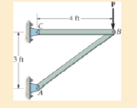
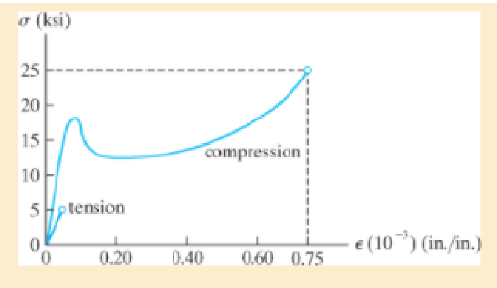
The two bars are made of a material that has the stress-strain diagram shown. If the cross-sectional area of bar AB is 1.5 in2 and BC is 4 in2, determine the largest force P that can be supported before any member fractures. Assume that buckling does not occur.
Expert Solution & Answer
Want to see the full answer?
Check out a sample textbook solution
Students have asked these similar questions
1. The rotating steel shaft is simply supported by bearings at points of B and C, and is driven by a spur
gear at D, which has a 6-in pitch diameter. The force F from the drive gear acts at a pressure angle of
20°. The shaft transmits a torque to point A of TA =3000 lbĘ in. The shaft is machined from steel with
Sy=60kpsi and Sut=80 kpsi.
(1) Draw a shear force diagram and a bending moment diagram by F. According to your analysis, where is
the point of interest to evaluate the safety factor among A, B, C, and D? Describe the reason. (Hint: To find
F, the torque Tд is generated by the tangential force of F (i.e. Ftangential-Fcos20°)
When n=2.5, K=1.8, and K₁ =1.3, determine the diameter of the shaft based on
(2) static analysis using DE theory (note that fatigue stress concentration factors need to be used for this
question because the loading condition is fatigue) and
(3) a fatigue analysis using modified Goodman.
Note) A standard diameter is not required for the questions.
10 in
D
3
N2=28
P(diametral pitch)=8 for all gears
Coupled to 25 hp motor
N3=34
Full depth spur gears with pressure angle=20°
N₂=2000 rpm
(1) Compute the circular pitch, the center-to-center distance, and base circle radii.
(2) Draw the free body diagram of gear 3 and show all the forces and the torque.
(3) In mounting gears, the center-to-center distance was reduced by 0.1 inch.
Calculate the new values of center-to-center distance, pressure angle, base circle radii,
and pitch circle diameters.
(4)What is the new tangential and radial forces for gear 3?
(5) Under the new center to center distance, is the contact ratio (mc) increasing or
decreasing?
2. A flat belt drive consists of two 4-ft diameter cast-iron pulleys spaced 16 ft apart.
A power of 60 hp is transmitted by a pulley whose speed is 380 rev/min. Use a
service factor (Ks) pf 1.1 and a design factor 1.0. The width of the polyamide A-3
belt is 6 in. Use CD=1. Answer the following questions.
(1) What is the total length of the belt according to the given geometry?
(2) Find the centrifugal force (Fc) applied to the belt.
(3) What is the transmitted torque through the pulley system given 60hp?
(4) Using the allowable tension, find the force (F₁) on the tight side. What is the
tension at the loose side (F2) and the initial tension (F.)?
(5) Using the forces, estimate the developed friction coefficient (f)
(6) Based on the forces and the given rotational speed, rate the pulley set. In other
words, what is the horse power that can be transmitted by the pulley system?
(7) To reduce the applied tension on the tight side, the friction coefficient is
increased to 0.75. Find out the…
Chapter 3 Solutions
Mechanics Of Materials, Si Edition
Ch. 3.5 - Define a homogeneous material.Ch. 3.5 - Indicate the points on the stress-strain diagram...Ch. 3.5 - Define the modulus of elasticity E.Ch. 3.5 - At room temperature, mild steel is a ductile...Ch. 3.5 - Engineering stress and strain are calculated using...Ch. 3.5 - As the temperature increases the modulus of...Ch. 3.5 - A 100-mm-long rod has a diameter of 15 mm. If an...Ch. 3.5 - A bar has a length of 8 in. and cross-sectional...Ch. 3.5 - A 10-mm-diameter rod has a modulus of elasticity...Ch. 3.5 - The material for the 50-mm-long specimen has the...
Ch. 3.5 - The material for the 50-mm-long specimen has the...Ch. 3.5 - If the elongation of wire BC is 0.2 mm after the...Ch. 3.5 - A tension test was performed on a steel specimen...Ch. 3.5 - Data taken from a stress-strain test for a ceramic...Ch. 3.5 - Data taken from a stress-strain test for a ceramic...Ch. 3.5 - Prob. 3.4PCh. 3.5 - 3-5. A tension test was performed on a steel...Ch. 3.5 - 3-6. A specimen is originally 1 ft long, has a...Ch. 3.5 - Prob. 3.7PCh. 3.5 - Prob. 3.8PCh. 3.5 - 3-9. The ?-? diagram for elastic fibers that make...Ch. 3.5 - Prob. 3.10PCh. 3.5 - Prob. 3.11PCh. 3.5 - Prob. 3.12PCh. 3.5 - A bar having a length of 5 in. and cross-sectional...Ch. 3.5 - The rigid pipe is supported by a pin at A and an...Ch. 3.5 - Prob. 3.15PCh. 3.5 - Prob. 3.16PCh. 3.5 - Prob. 3.17PCh. 3.5 - Prob. 3.18PCh. 3.5 - The stress-strain diagram for a bone is shown, and...Ch. 3.5 - The stress-strain diagram for a bone is shown and...Ch. 3.5 - The two bars are made of a material that has the...Ch. 3.5 - The two bars are made of a material that has the...Ch. 3.5 - Prob. 3.23PCh. 3.5 - Prob. 3.24PCh. 3.8 - A 100-mm-long rod has a diameter of 15 mm. If an...Ch. 3.8 - A solid circular rod that is 600 mm long and 20 mm...Ch. 3.8 - A 20-mm-wide block is firmly bonded to rigid...Ch. 3.8 - A 20-mm-wide block is bonded to rigid plates at...Ch. 3.8 - The acrylic plastic rod is 200 mm long and 15 mm...Ch. 3.8 - 3–26. The thin-walled tube is subjected to an...Ch. 3.8 - 3-27. When the two forces are placed on the beam,...Ch. 3.8 - Prob. 3.28PCh. 3.8 - Prob. 3.29PCh. 3.8 - The lap joint is connected together using a 1.25...Ch. 3.8 - The lap joint is connected together using a 1.25...Ch. 3.8 - Prob. 3.32PCh. 3.8 - Prob. 3.33PCh. 3.8 - A shear spring is made from two blocks of rubber,...Ch. 3 - The elastic portion of the tension stress-strain...Ch. 3 - The elastic portion of the tension stress-strain...Ch. 3 - The rigid beam rests in the horizontal position on...Ch. 3 - The wires each have a diameter of 12 in., length...Ch. 3 - The wires each have a diameter of 12 in., length...Ch. 3 - diameter steel bolts. If the clamping force in...Ch. 3 - The stress-strain diagram for polyethylene, which...Ch. 3 - The pipe with two rigid caps attached to its ends...Ch. 3 - The 8-mm-diameter bolt is made of an aluminum...Ch. 3 - An acetal polymer block is fixed to the rigid...
Knowledge Booster


Learn more about
Need a deep-dive on the concept behind this application? Look no further. Learn more about this topic, mechanical-engineering and related others by exploring similar questions and additional content below.Similar questions
- The tooth numbers for the gear train illustrated are N₂ = 24, N3 = 18, №4 = 30, №6 = 36, and N₁ = 54. Gear 7 is fixed. If shaft b is turned through 5 revolutions, how many turns will shaft a make? a 5 [6] barrow_forwardCE-112 please solve this problem step by step and give me the correct answerarrow_forwardCE-112 please solve this problem step by step and give me the correct answerarrow_forward
- CE-112 solve this problem step by step and give me the correct answer pleasearrow_forwardPlease do not use any AI tools to solve this question. I need a fully manual, step-by-step solution with clear explanations, as if it were done by a human tutor. No AI-generated responses, please.arrow_forwardPlease do not use any AI tools to solve this question. I need a fully manual, step-by-step solution with clear explanations, as if it were done by a human tutor. No AI-generated responses, please.arrow_forward
arrow_back_ios
SEE MORE QUESTIONS
arrow_forward_ios
Recommended textbooks for you
 Mechanics of Materials (MindTap Course List)Mechanical EngineeringISBN:9781337093347Author:Barry J. Goodno, James M. GerePublisher:Cengage Learning
 International Edition---engineering Mechanics: St...Mechanical EngineeringISBN:9781305501607Author:Andrew Pytel And Jaan KiusalaasPublisher:CENGAGE L
Mechanics of Materials (MindTap Course List)
Mechanical Engineering
ISBN:9781337093347
Author:Barry J. Goodno, James M. Gere
Publisher:Cengage Learning
International Edition---engineering Mechanics: St...
Mechanical Engineering
ISBN:9781305501607
Author:Andrew Pytel And Jaan Kiusalaas
Publisher:CENGAGE L
Stresses Due to Fluctuating Loads Introduction - Design Against Fluctuating Loads - Machine Design 1; Author: Ekeeda;https://www.youtube.com/watch?v=3FBmQXfP_eE;License: Standard Youtube License