
Engineering Mechanics: Statics and Study Pack (13th Edition)
13th Edition
ISBN: 9780133027990
Author: Russell C. Hibbeler
Publisher: Prentice Hall
expand_more
expand_more
format_list_bulleted
Concept explainers
Videos
Textbook Question
Chapter 3.4, Problem 9FP
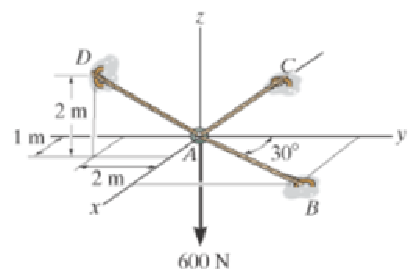
Determine the tension developed in cables AB, AC, and AD.
Expert Solution & Answer

Learn your wayIncludes step-by-step video

schedule07:03
Students have asked these similar questions
practice problems want detailed break down
6.105. Determine force P on the cable if the spring is compressed 0.025 m when the mechanism is in the
position shown. The spring has a stiffness of k = 6 kN/m.
E
P
150 mm
D
T
30°
200 mm
200 mm
200 mm
B
800 mm
6.71. Determine the reactions at the supports A, C, and E of the compound beam.
3 kN/m
12 kN
A
B
CD
E
-3 m 4 m
6 m
3 m
2 m
Chapter 3 Solutions
Engineering Mechanics: Statics and Study Pack (13th Edition)
Ch. 3.3 - Determine the force in each supporting cable.Ch. 3.3 - Determine the shortest cable ABC that can be used...Ch. 3.3 - Neglect the size of the pulley.Ch. 3.3 - Determine the unstretched length of the spring.Ch. 3.3 - If the mass of cylinder C is 40 kg, determine the...Ch. 3.3 - Also, find the angle .Ch. 3.3 - Determine the magnitudes of F1 and F2 for...Ch. 3.3 - Determine the magnitude of F1 and its angle for...Ch. 3.3 - Determine the force in each of the cables AB and...Ch. 3.3 - Prob. 4P
Ch. 3.3 - Prob. 5PCh. 3.3 - Prob. 6PCh. 3.3 - Prob. 7PCh. 3.3 - Prob. 8PCh. 3.3 - Determine the maximum weight of the flowerpot that...Ch. 3.3 - Prob. 10PCh. 3.3 - Prob. 11PCh. 3.3 - Prob. 12PCh. 3.3 - Prob. 13PCh. 3.3 - Prob. 14PCh. 3.3 - Prob. 15PCh. 3.3 - Prob. 16PCh. 3.3 - Note that s = 0 when the cylinders are removed.Ch. 3.3 - The springs are shown in the equilibrium position.Ch. 3.3 - If the block is held in the equilibrium position...Ch. 3.3 - Determine the horizontal force F applied to the...Ch. 3.3 - Determine the displacement d of the cord from the...Ch. 3.3 - If the spring has an unstretched length of 2 ft,...Ch. 3.3 - Cord AB is 2 ft long. Take k = 50 lb/ft.Ch. 3.3 - Prob. 24PCh. 3.3 - Prob. 25PCh. 3.3 - Prob. 26PCh. 3.3 - Prob. 27PCh. 3.3 - Determine the tension developed in each cord...Ch. 3.3 - Determine the maximum mass of the lamp that the...Ch. 3.3 - Prob. 30PCh. 3.3 - Prob. 31PCh. 3.3 - Prob. 32PCh. 3.3 - Prob. 33PCh. 3.3 - Prob. 34PCh. 3.3 - Determine the position x and the tension developed...Ch. 3.3 - Determine the position x and the tension in the...Ch. 3.3 - If the cable can be attached at either points A...Ch. 3.3 - Prob. 38PCh. 3.3 - The cord is fixed to a pin at A and passes over...Ch. 3.3 - Prob. 40PCh. 3.3 - Take F = 300 N and d = 1 m.Ch. 3.3 - If a force of F = 100 N is applied horizontally to...Ch. 3.3 - Establish appropriate dimensions and use an...Ch. 3.3 - If the maximum tension that can be supported by...Ch. 3.3 - If the angle between AB and BC is 30, determine...Ch. 3.3 - If the distance BC is 1.5 m, and AB can support a...Ch. 3.4 - Determine the magnitude of forces F1, F2, F3, so...Ch. 3.4 - Determine the tension developed in cables AB, AC,...Ch. 3.4 - Determine the tension developed in cables AB, AC,...Ch. 3.4 - F310. Determine the tension developed in cables...Ch. 3.4 - Determine the tension in these wires.Ch. 3.4 - Prob. 43PCh. 3.4 - If cable AB is subjected to a tension of 700 N,...Ch. 3.4 - Determine the magnitudes of F1, F2, and F3 for...Ch. 3.4 - If the bucket and its contents have a total weight...Ch. 3.4 - Each spring has on unstretched length of 2 m and a...Ch. 3.4 - Prob. 48PCh. 3.4 - Prob. 49PCh. 3.4 - Prob. 50PCh. 3.4 - Prob. 51PCh. 3.4 - Prob. 52PCh. 3.4 - Prob. 53PCh. 3.4 - Determine the tens on developed in cables AB and...Ch. 3.4 - Also, what is the force developed along strut AD?Ch. 3.4 - Prob. 56PCh. 3.4 - Prob. 57PCh. 3.4 - Determine the tension developed in each cable for...Ch. 3.4 - Determine the maximum weight of the crate that can...Ch. 3.4 - Determine the force in each chain for equilibrium....Ch. 3.4 - If cable AD is tightened by a turnbuckle and...Ch. 3.4 - If cable AD is tightened by a turnbuckle and...Ch. 3.4 - Prob. 63PCh. 3.4 - Prob. 64PCh. 3.4 - Prob. 65PCh. 3.4 - Prob. 66PCh. 3.4 - Prob. 67PCh. 3.4 - If the bolt exerts a force of 50 lb on the pipe in...Ch. 3.4 - Determine the magnitude of the applied vertical...Ch. 3.4 - Prob. 70RPCh. 3.4 - Prob. 71RPCh. 3.4 - Prob. 72RPCh. 3.4 - Prob. 73RPCh. 3.4 - Also, what is the force in cord AB? Hint: use the...Ch. 3.4 - Prob. 75RPCh. 3.4 - Determine the force in each cable needed to...Ch. 3.4 - Prob. 77RP
Additional Engineering Textbook Solutions
Find more solutions based on key concepts
Distinguish among data definition commands, data manipulation commands, and data control commands.
Modern Database Management
Write a recursive method that will compute the sum of all the values in an array.
Java: An Introduction to Problem Solving and Programming (8th Edition)
Suppose the memory cells at addresses 0x00 through 0x05 in the Vole contain the following bit patterns: Address...
Computer Science: An Overview (13th Edition) (What's New in Computer Science)
TeamLeader Class In a particular factory, a team leader is an hourly paid production worker that leads a small ...
Starting Out with Java: From Control Structures through Objects (7th Edition) (What's New in Computer Science)
The same formatting techniques used with _______________ may also be used when writing data to a file.
Starting Out with C++ from Control Structures to Objects (9th Edition)
List the five major hardware components of a computer system.
Starting Out With Visual Basic (8th Edition)
Knowledge Booster


Learn more about
Need a deep-dive on the concept behind this application? Look no further. Learn more about this topic, mechanical-engineering and related others by exploring similar questions and additional content below.Similar questions
- A countershaft carrying two V-belt pullets is shown in the figure. Pulley A receives power from a motor through a belt with the belt tensions shown. The power is transmitted through the shaft and delivered to the belt on pulley B. Assume the belt tension on the loose side (T1) at B is 30% of the tension on the tight side (T2). (a) Determine the tension (i.e., T₂ and T₁) in the belt on pulley B, assuming the shaft is running at a constant speed. (b) Find the magnitudes of the bearing reaction forces, assuming the bearings act as simple supports. (c) Draw shear-force and bending moment diagrams for the shaft (in XZ and XY plane if needed). (d) Calculate the maximum moments at points A and B respectively and find the point of maximum bending moment (A or B). (e) Find maximum stresses (tensile, compressive, and shear stresses) at the identified point of maximum moment (hint: principal and max shear stresses) 8 dia. 9 400lbf 50lbf 45° 1.5 dia. T₂ B Units in inches T₁ 10 dia.arrow_forwardThe cantilevered bar in the figure is made from a ductile material and is statically loaded with F,, = 200 lbf and Fx = F₂ = 0. Analyze the stress situation in rod AB by obtaining the following information. Note that the stress concentration factors are neglected in the following questions (Kt and Kts=1). (a) Determine the precise location of the critical stress element. (b) Sketch the critical stress element and determine magnitudes and direction for all stresses acting on it. (Transverse shear may only be neglected if you can justify this decision.) (c) For the critical stress element, determine the principal stresses and maximum shear stress. 6 in 1-in dia. B +1- in in 2 in 5 inarrow_forwardA laminated thick-walled hydraulic cylinder was fabricated by shrink-fitting jacket having an outside diameter of 300mm onto a SS 304 steel tube having an inside diameter of 100mm and an outside diameter of 200mm as shown in the figure. The interference (8) was 0.15mm. When the Young's modulus for both SS304 and 1020 steel is the same as 200GPa, and the Poisson's ratio is also the same as 0.3 for both materials, find the followings. Initially 100 mm Initially 200 mm Initially 300 mm SS 304 1020 steel (a) P; (interfacial contact stress) (b) The maximum stresses (σ, and σ+) in the laminated steel cylinder resulting from the shrink fit.arrow_forward
- Auto Controls Design a proportional derivitivecontroller for a plant orsystemthat satisfies the following specifications : 1. is steady-state error is less than 2 % for a ramp input. 2.) Damping ratio (zeta) is greater than 0.7have determined the 3. Once youvalue of kp and kd, then plotthe response of the compensated(with controller) and uncompensated( without the controller, only the plantsystem using MATLAB.arrow_forwardAuto Controls (a) Refer to the above figure .What kind of controller is it ? (b) simplify the block diagramto derive the closed loop transfer function of the system. (C) What are the assumptions thatare needed to make to findthe controller gain ? What arethe value of Kp , Ti and Td ?arrow_forwardAuto Controls Design a PID controller for thefollowing system so that the modified system satisfies the followingspecifications : 1. settling time ,ts = 1.96 s and % Overshoot Mp = 70.7 % Assume a non-dominant pole at s = -15 to solve the problem The plot the compensated andThen plot the uncompensated system in MATLAB. what can you see from the plot ? what is your observation ?arrow_forward
- Fourth year Monthly exam\3 2024-2025 Power plant Time: 1 Hr Q1. A gas turbine power plant operates on a modified Brayton cycle consisting of two-stage compression with intercooling to the initial temperature between stages, two-stage expansion with reheating to the maximum cycle temperature, and two regenerative heat exchangers. The following data is given: Inlet air temperature: 300 K Maximum cycle temperature: 1400 K Pressure ratio across each compressor stage: 4 Pressure ratio across each turbine stage: 4 Isentropic efficiency of compressors and turbines: 85% Effectiveness of each regenerator: 80% a) Draw a schematic and T-s diagram of the cycle. b) Determine the thermal efficiency of the cycle. c) Calculate the net specific work output (in kJ/kg). d) Discuss the impact of regenerators on the cycle performance. Examiner Prof. Dr. Adil Al-Kumaitarrow_forwardAuto Controls The figure is a schematic diagram of an aircraft elevator control system. The input to the systemin the deflection angle of the control lever , and the output is the elevator angle phi.show that for each angle theta of the control lever ,there is a corresponding elevator angle phi. Then find Y(s)/theta(s) and simplify the resulting transfer function . Also note from the diagram that y and phi is relatedarrow_forwardLiquid hexane flows through a counter flow heat exchanger at 5 m3/h as shown in Figure E5.5.The hexane enters the heat exchanger at 90°C. Water, flowing at 5 m3/h, is used to cool the hexane.The water enters the heat exchanger at 15°C. The UA product of the heat exchanger is found to be2.7 kW/K. Determine the outlet temperatures of the hot and cold fluids and the heat transfer ratebetween them using LMTD method.arrow_forward
- Determine the fluid outlet temperatures and the heat transfer rate for the counter flow heatexchanger described in Problem 3 using the ε-NTU model. Assume that the properties can beevaluated at the given fluid inlet temperatures.arrow_forwardSection View - practice Homework 0.5000 3.0000 2,0000 1.0000arrow_forwardDrawing the section view for the following multiview drawing AutoCAD you see the section pratice I need to show how to autocadarrow_forward
arrow_back_ios
SEE MORE QUESTIONS
arrow_forward_ios
Recommended textbooks for you
 International Edition---engineering Mechanics: St...Mechanical EngineeringISBN:9781305501607Author:Andrew Pytel And Jaan KiusalaasPublisher:CENGAGE L
International Edition---engineering Mechanics: St...
Mechanical Engineering
ISBN:9781305501607
Author:Andrew Pytel And Jaan Kiusalaas
Publisher:CENGAGE L
Engineering Basics - Statics & Forces in Equilibrium; Author: Solid Solutions - Professional Design Solutions;https://www.youtube.com/watch?v=dQBvQ2hJZFg;License: Standard YouTube License, CC-BY