Videos
(a)
The phasor diagram if the capacitance is
(a)
Answer to Problem 66PQ
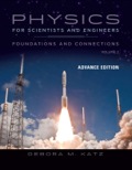
The phasor diagram of the circuit is shown below.
Explanation of Solution
Write the expression for the impedance.
Here,
Write the expression to calculate the inductive reactance.
Here,
Write the expression for the capacitive reactance.
Here,
Substitute the
Write the expression for maximum current in the circuit.
Here,
Write the expression for phase angle.
Conclusion:
Substitute
Substitute
Substitute
The phase angle is
The inductive reactance is less than the capacitive reactance. Hence, the phasor angle is negative.
The phasor diagram of the circuit is shown below. 
Figure (1)
(b)
The phasor diagram if the capacitance is
(b)
Answer to Problem 66PQ
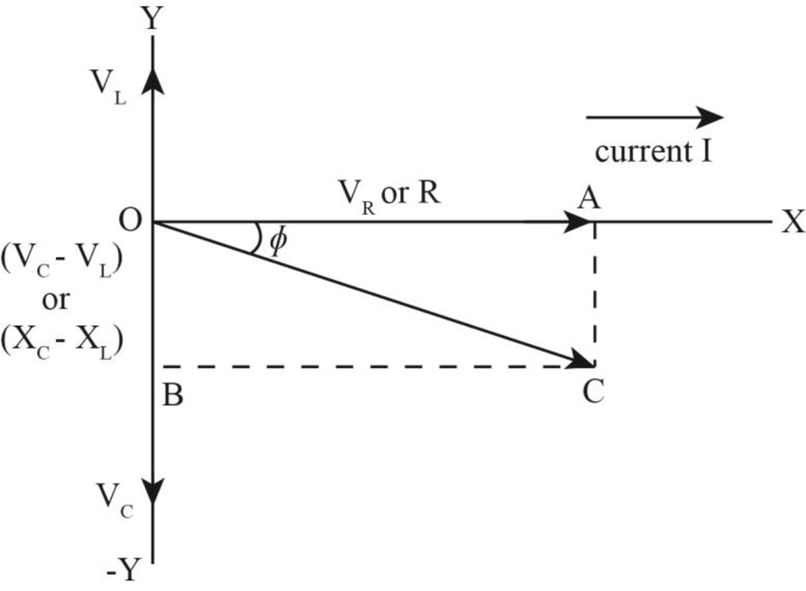
The phasor diagram of the circuit is shown below.
Explanation of Solution
Write the expression for the impedance.
Here,
Write the expression to calculate the inductive reactance.
Here,
Write the expression for the capacitive reactance.
Here,
Substitute the
Write the expression for maximum current in the circuit.
Here,
Write the expression for phase angle.
Conclusion:
Substitute
Substitute
Substitute
The phase angle is
The inductive reactance is less than the capacitive reactance. Hence, the phasor angle is negative.
The phasor diagram of the circuit is shown below.

Want to see more full solutions like this?
Chapter 33 Solutions
EBK PHYSICS FOR SCIENTISTS AND ENGINEER


- no ai pleasearrow_forwardA block of mass m₁ = 1.85 kg and a block of mass m₂ is 0.360 for both blocks. = m M, R m2 Ꮎ 5.90 kg are connected by a massless string over a pulley in the shape of a solid disk having a mass of M = 10.0 kg. The fixed, wedge-shaped ramp makes an angle of 0 = 30.0° as shown in the figure. The coefficient of kinetic friction (a) Determine the acceleration of the two blocks. (Enter the magnitude of the acceleration.) x m/s² (b) Determine the tensions in the string on both sides of the pulley. left of the pulley × N right of the pulley X N Enter a number.arrow_forwardWhat is the error determined by the 2/3 rule?arrow_forward
- Your colleague gives you a sample that are supposed to consist of Pt-Ni nanoparticles, TiO2 nanorod arrays, and SiO2 monolith plates (see right panel schematic). The bimetallic Pt-Ni nanoparticles are expected to decorate on the side surfaces of the aligned TiO2 nanorod arrays. These aligned TiO2 nanoarrays grew on the flat SiO2 monolith. Let's assume that the sizes of the Pt-Ni nanoparticles are > 10 nm. We further assume that you have access to a modern SEM that can produce a probe size as small as 1 nm with a current as high as 1 nA. You are not expected to damage/destroy the sample. Hint: keep your answers concise and to the point. TiO₂ Nanorods SiO, monolith a) What do you plan to do if your colleague wants to know if the Pt and Ni formed uniform alloy nanoparticles? (5 points) b) If your colleague wants to know the spatial distribution of the PtNi nanoparticles with respect to the TiO2 nanoarrays, how do you accomplish such a goal? (5 points) c) Based on the experimental results…arrow_forwardFind the current in 5.00 and 7.00 Ω resistors. Please explain all reasoningarrow_forwardFind the amplitude, wavelength, period, and the speed of the wave.arrow_forward
- A long solenoid of length 6.70 × 10⁻² m and cross-sectional area 5.0 × 10⁻⁵ m² contains 6500 turns per meter of length. Determine the emf induced in the solenoid when the current in the solenoid changes from 0 to 1.5 A during the time interval from 0 to 0.20 s. Number Unitsarrow_forwardA coat hanger of mass m = 0.255 kg oscillates on a peg as a physical pendulum as shown in the figure below. The distance from the pivot to the center of mass of the coat hanger is d = 18.0 cm and the period of the motion is T = 1.37 s. Find the moment of inertia of the coat hanger about the pivot.arrow_forwardReview Conceptual Example 3 and the drawing as an aid in solving this problem. A conducting rod slides down between two frictionless vertical copper tracks at a constant speed of 3.9 m/s perpendicular to a 0.49-T magnetic field. The resistance of th rod and tracks is negligible. The rod maintains electrical contact with the tracks at all times and has a length of 1.4 m. A 1.1-Q resistor is attached between the tops of the tracks. (a) What is the mass of the rod? (b) Find the change in the gravitational potentia energy that occurs in a time of 0.26 s. (c) Find the electrical energy dissipated in the resistor in 0.26 s.arrow_forward
- A camera lens used for taking close-up photographs has a focal length of 21.5 mm. The farthest it can be placed from the film is 34.0 mm. (a) What is the closest object (in mm) that can be photographed? 58.5 mm (b) What is the magnification of this closest object? 0.581 × ×arrow_forwardGiven two particles with Q = 4.40-µC charges as shown in the figure below and a particle with charge q = 1.40 ✕ 10−18 C at the origin. (Note: Assume a reference level of potential V = 0 at r = ∞.) Three positively charged particles lie along the x-axis of the x y coordinate plane.Charge q is at the origin.Charge Q is at (0.800 m, 0).Another charge Q is at (−0.800 m, 0).(a)What is the net force (in N) exerted by the two 4.40-µC charges on the charge q? (Enter the magnitude.) N(b)What is the electric field (in N/C) at the origin due to the two 4.40-µC particles? (Enter the magnitude.) N/C(c)What is the electrical potential (in kV) at the origin due to the two 4.40-µC particles? kV(d)What If? What would be the change in electric potential energy (in J) of the system if the charge q were moved a distance d = 0.400 m closer to either of the 4.40-µC particles?arrow_forward(a) Where does an object need to be placed relative to a microscope in cm from the objective lens for its 0.500 cm focal length objective to produce a magnification of -25? (Give your answer to at least three decimal places.) 0.42 × cm (b) Where should the 5.00 cm focal length eyepiece be placed in cm behind the objective lens to produce a further fourfold (4.00) magnification? 15 × cmarrow_forward
 Physics for Scientists and Engineers: Foundations...PhysicsISBN:9781133939146Author:Katz, Debora M.Publisher:Cengage Learning
 College PhysicsPhysicsISBN:9781285737027Author:Raymond A. Serway, Chris VuillePublisher:Cengage Learning
 College PhysicsPhysicsISBN:9781305952300Author:Raymond A. Serway, Chris VuillePublisher:Cengage Learning
 Physics for Scientists and EngineersPhysicsISBN:9781337553278Author:Raymond A. Serway, John W. JewettPublisher:Cengage Learning
 Physics for Scientists and Engineers with Modern ...PhysicsISBN:9781337553292Author:Raymond A. Serway, John W. JewettPublisher:Cengage Learning